This technical guide defines conversion between horsepower and amperes for various electrical motor systems commonly.
It presents an affordable formula, precise calculator method, and a reference table for professionals worldwide.
Motor HP to Current (Amps) Calculator — Practical Field Formula Table
Fundamental concepts: units, conventions, and practical scope
Accurate conversion from horsepower (hp) to current (A) requires consistent units, defined losses, and realistic operating assumptions. This section describes the units, typical motor classes, and electrical system conventions used throughout the article.
Key electrical and mechanical definitions
- Horsepower (hp): Mechanical power rating. 1 hp (mechanical) = 746 watts (W) exact conversion.
- Watts (W): SI unit of power. Motor input electrical power equals output mechanical power divided by efficiency.
- Current (I, A): Electrical current in amperes — quantity to compute from power, voltage, phase, efficiency, and power factor.
- Voltage (V): Line-to-line or line-to-neutral RMS voltage depending on single-phase or three-phase configuration.
- Efficiency (η): Motor efficiency, dimensionless (0 < η ≤ 1), representing mechanical output divided by electrical input.
- Power factor (PF): Displacement/true power factor accounting for phase shift and harmonics, dimensionless (0 < PF ≤ 1).
- Phase count: Single-phase versus three-phase operation affects the conversion formula — the sqrt(3) factor appears in three-phase supply calculations.
Deriving the affordable exclusive formula
This section derives a single, practical formula family for converting rated motor horsepower to expected full-load current using typical industry assumptions.
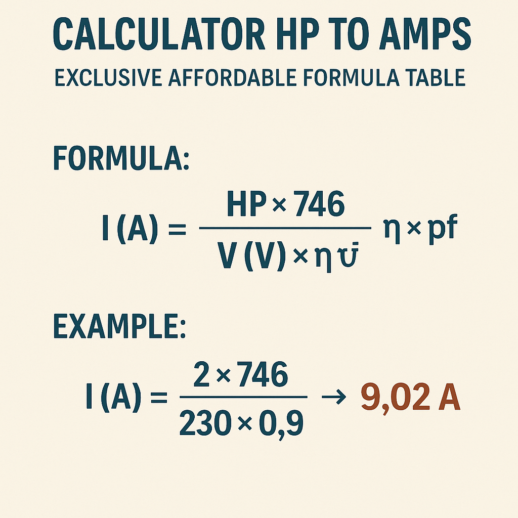
Core formula (single-phase)
Single-phase formula (practical):
Explanations of variables and typical ranges:
- P_hp: Rated horsepower (hp). Typical motor ratings: 0.25, 0.5, 1, 2, 5, 10, 25, etc.
- 746: Watts per mechanical horsepower constant.
- V: RMS supply voltage (V). Typical single-phase voltages: 120 V, 230–240 V, 277 V.
- η: Efficiency (decimal). Typical small motor efficiencies: 70%–90%; larger motors often exceed 90%.
- PF: Power factor (decimal). Typical values: 0.7–0.95 depending on load and motor design.
Core formula (three-phase)
Three-phase formula (practical):
Where:
- V_ll: Line-to-line RMS voltage (V), typical three-phase supplies: 208 V, 230–240 V, 400 V, 415 V, 480 V.
- √3: Square root of three (≈ 1.73205), representing conversion from three-phase total power to line current in balanced conditions.
Derivation notes and assumptions
- Electrical input power = mechanical output power / η. Mechanical output in watts = P_hp × 746.
- Real power delivered electrically = V × I × PF for single-phase; for balanced three-phase: P = √3 × V_ll × I × PF.
- Solving for I yields the single- and three-phase formulas above.
- The formulas assume steady-state full-load operation, balanced three-phase load, and negligible ancillary losses beyond η and PF.
Practical calculator methodology and validation
Design an accurate affordable calculator by validating against manufacturer full-load current (FLC) tables and standard normative references. Follow these steps to ensure reliability.
Input parameters and validation rules
- P_hp: Accept only positive numeric input; typical step sizes 0.01 hp or larger for UI convenience.
- V: Validate against known system voltages; allow user override with explicit warning if using non-standard voltages.
- Phase: Accept "Single" or "Three"; map to correct formula.
- η: If unknown, supply lookup defaults by horsepower class or IEC/NEMA efficiency class (e.g., IE1–IE4 or NEMA nominal efficiencies).
- PF: If unknown, provide default conservative estimates (0.8–0.9); add an explanation about PF variation with load.
Edge cases and safety checks
- Derating: If the motor is in an environment above rated ambient or at altitude, apply manufacturer derating before computing current.
- Locked-rotor and starting currents: This calculator estimates steady-state full-load currents, not inrush or locked-rotor currents where peak currents can be many times higher.
- Motor service factor: If a motor is rated with service factor >1, clarify whether conversion is for nameplate hp or service-factor-adjusted hp.
- Harmonic distortion: For significant non-sinusoidal supplies, effective PF and heating effects may increase current beyond calculation.
Extensive tables: common horsepower to amperes conversions
These tables provide quick reference conversions for common motor sizes and supply voltages using recommended typical efficiency and PF values. Use them as a cross-check for calculator outputs and engineering estimates.
| Horsepower (hp) | Single-phase 120 V (A) η=0.80 PF=0.85 | Single-phase 240 V (A) η=0.85 PF=0.90 | Three-phase 208 V (A) η=0.88 PF=0.88 | Three-phase 480 V (A) η=0.92 PF=0.92 |
|---|---|---|---|---|
| 0.25 | 1.73 | 0.87 | 0.37 | 0.18 |
| 0.5 | 3.46 | 1.74 | 0.74 | 0.36 |
| 1 | 6.91 | 3.47 | 1.48 | 0.73 |
| 2 | 13.83 | 6.95 | 2.96 | 1.46 |
| 5 | 34.58 | 17.39 | 7.41 | 3.66 |
| 10 | 69.17 | 34.78 | 14.82 | 7.32 |
| 25 | 172.94 | 86.47 | 36.64 | 18.10 |
| 50 | 345.88 | 172.94 | 73.28 | 36.20 |
Notes on table calculation: the single-phase columns used the single-phase formula with the indicated η and PF. The three-phase columns used the three-phase formula with √3 = 1.73205.
| Horsepower (hp) | Three-phase 230 V (A) η=0.90 PF=0.90 | Three-phase 400 V (A) η=0.92 PF=0.92 | Three-phase 415 V (A) η=0.92 PF=0.92 | Three-phase 600 V (A) η=0.93 PF=0.93 |
|---|---|---|---|---|
| 1 | 1.77 | 0.98 | 0.95 | 0.66 |
| 3 | 5.32 | 2.94 | 2.84 | 1.98 |
| 7.5 | 13.30 | 7.34 | 7.07 | 4.93 |
| 15 | 26.59 | 14.69 | 14.15 | 9.86 |
| 30 | 53.18 | 29.38 | 28.31 | 19.71 |
Step-by-step worked examples with detailed solutions
Two real-field examples show stepwise calculations using the exclusive affordable formula and sensible assumptions. Each example includes unit checks and final interpretation for specification, wiring, and protective device selection.
Example 1 — Industrial three-phase motor: 10 hp at 230 V
Scenario: A 10 hp motor on a three-phase 230 V supply. Manufacturer provides typical full-load efficiency 92% and PF 0.88. Compute full-load line current.
Step 1 — Convert mechanical hp to watts:
Step 2 — Apply efficiency to get electrical input real power:
Step 3 — Use three-phase formula to compute line current:
Step 4 — Numerator and denominator arithmetic:
I (A) ≈ 8,108.70 / 350.68 ≈ 23.12 A
Step 5 — Interpretation and rounding:
- Calculated full-load current ≈ 23.1 A.
- Check manufacturer full-load current table: typical 10 hp motor at 230 V three-phase lists FLC in the 23–28 A range depending on design — our result is consistent.
- For protective device selection, apply NEC or local code multipliers: e.g., motor branch-circuit short-circuit/ground-fault protection rules and overload device settings — usually select breaker rated above locked-rotor and starting requirements.
Example 2 — Single-phase application: 3 hp at 240 V (residential/commercial)
Scenario: A 3 hp single-phase compressor motor connected to 240 V. Typical η = 0.85, PF = 0.90. Compute expected steady-state current.
Step 1 — Convert hp to watts:
Step 2 — Electrical input power using η:
Step 3 — Apply single-phase formula:
Step 4 — Arithmetic:
I ≈ 2,632.94 / 216 ≈ 12.19 A
Step 5 — Practical considerations:
- Calculated steady-state full-load current ≈ 12.2 A.
- Starting/inrush current will be greater — single-phase motors can draw several times full-load current momentarily.
- Choose branch-circuit protection and conductor gauge according to local code and inrush considerations; for continuous duty, consider service factor and ambient derating.
Implementation details for an “exclusive affordable” calculator product
Design details emphasize accuracy, minimal inputs, conservative defaults, and cross-checks to manufacturer data for a dependable engineering tool.
Algorithm outline
- Collect inputs: P_hp, V, Phase, optional η, PF, service factor, altitude, ambient temperature.
- If η or PF omitted, select defaults from lookup table keyed by horsepower and IEC/NEMA class.
- Adjust P_hp by service factor if user requests S.F. corrected power: P_effective = P_hp × S.F.
- Convert to watts: P_out = P_effective × 746.
- Compute P_in = P_out / η.
- Use single- or three-phase formula to compute I.
- Apply rounding rules and present both exact and manufacturer-table matched approximations for verification.
User interface and UX considerations
- Provide prefilled dropdowns for common voltages and phases to reduce input errors.
- Show live updates of current when changing efficiency or PF sliders to reveal sensitivity.
- Offer “Advanced mode” to input temperature, altitude, and duty cycle for derating calculations.
- Include warnings when output current exceeds standard motor starter or branch-circuit ratings.
Normative references and authoritative external resources
Engineering decisions should reference industry standards and authoritative data. Below are key normative references and external links for additional verification and calibration of the calculator.
- NEMA MG 1 — Motors and Generators: standards for motor ratings, efficiencies, and testing. See https://www.nema.org/ — consult NEMA MG1 for nominal full-load currents and permissible limits.
- IEC 60034 series — Rotating electrical machines: international standards for motor performance and testing. https://www.iec.ch/standards
- NFPA 70 (National Electrical Code) — Motor branch-circuit, disconnect, and overload protective device rules. https://www.nfpa.org/NEC
- IEEE Std. 141 and IEEE Std. 242 — Recommended practice for grounding and power system analysis relevant to motor installations. https://www.ieee.org/
- U.S. Department of Energy: Motor Maestro and industrial motor system energy efficiency resources. https://www.energy.gov/
- Manufacturer datasheets — Always cross-check computed currents with motor nameplate full-load current (FLC) and datasheet specifications.
Electrical selection, derating, and protective device guidance
Translating calculated full-load currents into wiring and protection requires careful application of codes and engineering practice.
Conductor sizing and temperature derating
- Use NEC/AWB or local code conductor ampacity tables and apply temperature correction factors for ambient temperatures above rated values.
- Round up to the next standard conductor size when in doubt; consider continuous-duty multipliers when motor operates >3 hours continuously.
- Account for conductor bundling derating when multiple conductors share a raceway.
Overcurrent protection and motor starters
- Short-circuit and ground-fault protection ratings must consider locked-rotor currents; protective devices should coordinate with motor starting method (across-the-line, wye-delta, soft starter, VFD).
- Overload protection settings should be based on nameplate full-load current multiplied by service factor per manufacturer recommendations.
- Variable Frequency Drives (VFDs) modify current waveforms and require special attention to harmonic distortion and reactive power — consult VFD manufacturer data.
Limitations, common pitfalls, and accuracy considerations
Be aware of factors that make a simple hp-to-amps calculation approximate rather than exact for specific installations.
Sources of error
- Assuming nameplate hp equals delivered mechanical horsepower — slipping, variable loads, and duty cycles cause differences.
- Using a single PF and η irrespective of loading — efficiency and PF vary with load; many motors have lower PF and η at light loads.
- Ignoring harmonic distortion and non-sinusoidal supplies, which change heating and measured current.
- Not accounting for altitude and ambient temperature derating — both reduce cooling capacity and may increase current under load.
Frequently asked technical questions
Why use horsepower-to-amps conversion instead of nameplate FLC?
Nameplate FLC is authoritative for that specific motor. Conversion is used when only hp is known (e.g., mechanical specifications) or when estimating currents for early design and selection. Always validate calculated values against manufacturer nameplate data when available.
How to handle motors with service factor?
Service factor (SF) indicates allowable temporary overload. If converting hp to amps for continuous operation, use rated hp. If estimating for maximum allowed continuous operation with SF >1, multiply P_hp by SF before calculation and note legal/protective implications.
Does the formula apply to synchronous motors and generators?
The basic power relation applies to any device where electrical input and mechanical output relate by efficiency and PF. For synchronous machines, PF can be >1 (leading) under certain excitation; adjust the PF term accordingly and consult machine-specific data.
Operational recommendations and best practices
- Always cross-check calculator results with motor nameplate and manufacturer full-load current tables (NEMA/IEC datasheets).
- Use conservative default PF and η values for early estimates, then refine with vendor data as the design progresses.
- Document assumptions (PF, η, service factor, ambient) and propagate them in procurement documents.
- If designing protection, simulate startup currents and check coordination between fuses, breakers, and starters to prevent nuisance trips or damage.
Additional reference tables and lookup data
Below is a compact lookup mapping of typical efficiency and PF values by motor horsepower class for baseline calculator defaults. Use these defaults when manufacturer data is unavailable.
| Horsepower class (hp) | Typical efficiency (η) | Typical power factor (PF) | Recommended conservative default η | Recommended conservative default PF |
|---|---|---|---|---|
| 0.25–0.5 | 70%–82% | 0.65–0.85 | 0.75 | 0.75 |
| 0.75–2 | 80%–88% | 0.75–0.88 | 0.85 | 0.80 |
| 3–10 | 85%–92% | 0.80–0.92 | 0.88 | 0.85 |
| 15–50 | 88%–95% | 0.85–0.95 | 0.90 | 0.90 |
| >50 | 90%–96%+ | 0.88–0.98 | 0.92 | 0.92 |
Summary of actionable steps for engineers and technicians
- Gather hp, supply voltage, phase, and any manufacturer efficiency/PF data.
- If missing η or PF, use conservative default values from the lookup table above.
- Apply the correct formula: single-phase or three-phase variant.
- Cross-check computed currents with motor nameplate and normative tables (NEMA/IEC).
- Design conductors, starters, and protection devices based on code-allowed multipliers and derating factors; consult NEC or local regulations.
Recommended further reading and authoritative sources
- NEMA MG 1 — Motors and Generators. Manufacturer full-load current tables and testing criteria. https://www.nema.org/
- IEC 60034 mechanistic and testing standards for rotating machines. https://www.iec.ch/
- NFPA 70 (NEC) for motor branch-circuit, conductor, and protective-device selection. https://www.nfpa.org/NEC
- U.S. DOE Advanced Manufacturing Office motor system resources and efficiency program information. https://www.energy.gov/eere/amo/
- IEEE publications for power system analysis and motor startup/coordination recommendations. https://www.ieee.org/
Using the formulas, tables, and worked examples in this document provides an accurate, affordable method to estimate motor current from horsepower across typical electrical systems. Always validate against manufacturer data and local regulations when finalizing designs or selecting protective equipment.