Selecting the correct VFD power rating is crucial for motor control, automation, safety, and energy efficiency.
This guide explains VFD power calculation with formulas, variable breakdowns, tables, and real-world engineering examples.
VFD Power Rating Calculator (HP/kW)
Size your VFD based on motor power, voltage, PF, efficiency and derating (duty, altitude, temperature, single-phase input).
What this calculator does
Formulas used
Overload/derating: Ireq = I · (overload) / (derate factor).
Minimum VFD power: Pvfd,min = Pmotor · (overload) / (derate factor).
Typical derating defaults
Normal vs Heavy duty
Common Values for VFD Power Rating (HP and kW)
Below is a comprehensive table of commonly used motor power ratings and the corresponding VFD sizing (HP/kW), nominal current (Amps), and typical voltage levels at both 50 Hz and 60 Hz.
Standard Motor Power Ratings and Corresponding VFD Ratings
| Motor Power (HP) | Motor Power (kW) | Line Voltage (V) | Typical Current (A) @ 400V | Recommended VFD kW | IEC Frame Size | NEMA Frame |
|---|---|---|---|---|---|---|
| 0.5 | 0.37 | 230 / 400 / 480 | 1.2 | 0.75 | 71 | 56C |
| 1 | 0.75 | 230 / 400 / 480 | 2.4 | 1.1 | 80 | 143T |
| 2 | 1.5 | 230 / 400 / 480 | 4.2 | 1.5 | 90S | 145T |
| 3 | 2.2 | 230 / 400 / 480 | 6.0 | 2.2 | 90L | 182T |
| 5 | 3.7 | 230 / 400 / 480 | 9.6 | 4.0 | 112M | 184T |
| 7.5 | 5.5 | 230 / 400 / 480 | 13.5 | 5.5 | 132S | 213T |
| 10 | 7.5 | 230 / 400 / 480 | 18.0 | 7.5 | 160M | 215T |
| 15 | 11 | 230 / 400 / 480 | 25.0 | 11.0 | 160L | 254T |
| 20 | 15 | 230 / 400 / 480 | 32.0 | 15.0 | 180M | 256T |
| 30 | 22 | 230 / 400 / 480 | 45.0 | 22.0 | 200L | 284T |
| 50 | 37 | 400 / 480 | 73.0 | 37.0 | 280S | 324T |
| 75 | 55 | 400 / 480 | 108.0 | 55.0 | 315S | 365T |
| 100 | 75 | 400 / 480 | 145.0 | 75.0 | 355M | 405T |
Notes:
- Based on IEC 60034 and NEMA MG1 standards.
- Current values are nominal, based on typical 4-pole motors at 50/60 Hz.
- Voltage classes vary by region: 230V/400V (IEC), 208V/480V (NEMA/ANSI).
Key Formulas for Calculating VFD Power Rating
The selection of a VFD power rating is based on a variety of electrical and mechanical factors. The following formulas are essential for precise sizing.
1. Power Conversion Between HP and kW
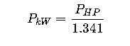
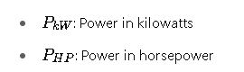
Common Values:
- 1 HP ≈ 0.746 kW
- 10 HP ≈ 7.46 kW
- 100 HP ≈ 74.6 kW
2. Output Power of the VFD
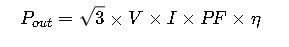
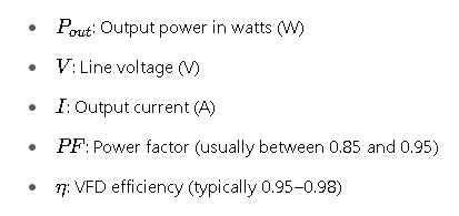
3. Motor Current (for 3-phase motors)
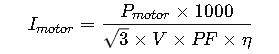
This formula is essential when calculating the VFD rating for motors of non-standard ratings or under unique loads.
4. VFD Oversizing (Service Factor)
A safety or service factor is often applied:
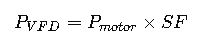
- Typical SF (Service Factor): 1.1 to 1.25
- Required when:
- Motor is running continuously at high load
- Ambient temperature exceeds 40°C
- High starting torque is required
Real-World Examples of VFD Power Rating Calculations
Example 1: Conveyor System in a Packaging Plant
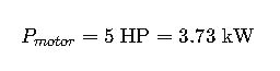
- Motor: 5 HP (3.7 kW)
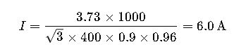
- Line Voltage: 400 V
- Power Factor: 0.9
- Efficiency: 0.96
Step-by-step:
1.Convert HP to kW:
2.Calculate motor current:
3.Select VFD:
- VFD must be rated at least 4 kW (next standard IEC rating)
- Choose VFD rated for ≥ 6.5 A output
Result: Select 4 kW VFD, 400V class, with current rating ≥ 6.5 A.
Example 2: HVAC Fan in a Commercial Building
- Motor: 15 HP (11 kW)
- Voltage: 480 V (NEMA)
- PF: 0.88
- Efficiency: 0.94
- Ambient Temp: 45°C (Requires oversizing)
Step-by-step:
1.Determine current:
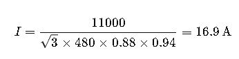
2.Apply service factor:
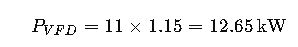
3.Choose next standard rating:
- 15 kW VFD, 480 V, ≥ 18 A output.
Result: Select 15 kW VFD, 480V, current ≥ 18 A.
Factors Influencing VFD Sizing Beyond Motor Power
1. Load Type (Torque Profile)
Different mechanical loads impose varying torque demands. This affects how a VFD should be sized and whether oversizing is needed.
| Load Type | Torque Demand | Typical Applications | VFD Sizing Factor |
|---|---|---|---|
| Constant Torque | Torque remains constant | Conveyors, mixers, compressors | 1.0× to 1.1× |
| Variable Torque | Torque ∝ speed² | Pumps, fans (centrifugal) | 1.0× |
| Shock/High Torque | Sudden torque spikes expected | Crushers, grinders, hoists | 1.15× to 1.25× |
Why It Matters:For high torque applications, oversizing the VFD is critical to avoid thermal overload and premature failure.
2. Ambient Temperature and Cooling
VFDs are typically rated for 40°C ambient. If installed in hotter environments:
- Above 40°C: Apply a derating factor (~2–3% per °C over 40°C).
- Above 50°C: May require external cooling or relocation.
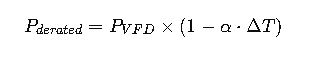
Where:
- α=0.02 to 0.03 per °C above rated
- ΔT: Difference from 40°C
3. Altitude Compensation
VFDs must also be derated for high-altitude installations (above 1000 m or 3300 ft)
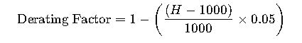
Where:
- H: Installation height in meters
Example:
At 3000 m altitude → derating of 10% ⇒ size a VFD 10% higher.
4. Starting Method & Duty Cycle
- Frequent starts/stops or acceleration ramps may require higher current capacity.
- Duty cycle exceeding 60% continuous torque operation → oversize by at least 10–20%.
Standards and Compliance in VFD Sizing
IEC Standards
- IEC 61800-2: Defines general requirements for VFDs
- IEC 60034-1: Covers motor ratings and permissible loading
- IEC 61000-4-2 to 61000-4-5: Covers EMI/EMC compatibility
🇺🇸 NEMA/ANSI Standards
- NEMA MG1 Part 31: Motors for use with adjustable-speed drives
- IEEE 519: Harmonic distortion limits in power systems
Harmonic Distortion (THD)
VFDs generate harmonics that must be filtered to protect the power system and meet IEEE 519 guidelines:
- Use line reactors or harmonic filters if:
- The motor is >15 HP
- THD > 5% at PCC (Point of Common Coupling)
Summary Checklist for Proper VFD Sizing
Before selecting your VFD, confirm the following:
✔️ Know the motor’s full load power in HP or kW
✔️ Identify the line voltage and frequency
✔️ Determine the motor current
✔️ Check the load type (constant or variable torque)
✔️ Factor in ambient temperature and altitude
✔️ Include service/oversizing factor
✔️ Ensure compliance with harmonic and EMC standards
✔️ Cross-check with manufacturer-specific VFD data sheets
Final Thoughts
Selecting a properly rated VFD is not simply a matter of matching the nameplate motor power. A variety of factors—load dynamics, environmental conditions, voltage levels, and operational duty—must be considered to ensure reliability, efficiency, and compliance.
By applying the formulas and best practices outlined in this article, electrical engineers, maintenance teams, and system designers can confidently select VFDs that maximize motor performance while minimizing risk and cost.