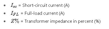
Short-circuit current is essential in transformer design, influenced by rating, impedance, voltage, and configuration.
This table presents typical short-circuit currents for common transformer sizes, assuming a worst-case three-phase fault.
Calculation of Short-Circuit Current in Transformers
Formulas used
What is %Z and where do I find it?
Symmetrical vs. asymmetrical fault
Scope and assumptions
Table 1: Common Transformer Short-Circuit Currents (Three-Phase Fault)
| Transformer Rating (kVA) | Primary Voltage (kV) | Secondary Voltage (V) | %Z (Impedance) | Fault Level (kA) | Short-Circuit MVA |
|---|---|---|---|---|---|
| 100 | 13.8 | 0.48 | 5.75% | 2.08 | 1.73 |
| 250 | 13.8 | 0.48 | 5.75% | 5.21 | 4.33 |
| 500 | 13.8 | 0.48 | 5.75% | 10.42 | 8.66 |
| 750 | 13.8 | 0.48 | 5.75% | 15.63 | 13.00 |
| 1000 | 13.8 | 0.48 | 5.75% | 20.83 | 17.32 |
| 1500 | 13.8 | 0.48 | 5.75% | 31.25 | 25.98 |
| 2000 | 13.8 | 0.48 | 5.75% | 41.66 | 34.64 |
| 2500 | 13.8 | 0.48 | 5.75% | 52.08 | 43.30 |
Note: These values assume no additional source impedance and no contribution from downstream motors. Always validate using system-specific data.
Key Formulas for Transformer Short-Circuit Current Calculation
Transformer short-circuit current calculation revolves around fundamental electrical formulas and per-unit systems. The primary formula is:
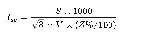
1. Short-Circuit Current at Transformer Secondary (Three-Phase):
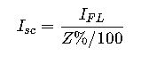
Where:
2. Full Load Current Calculation:
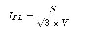
Where:
- S= Transformer apparent power (VA)
- V= Line-to-line voltage (V)
3. Short-Circuit MVA Calculation:

4. Available Fault Current at Secondary Terminals:
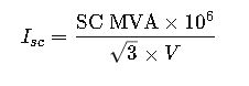
5. Fault Current from Short-Circuit MVA:
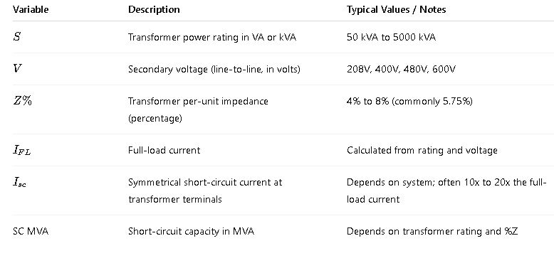
Explanation of Each Variable and Typical Ranges
Real-World Application Examples
Example 1: Short-Circuit Current of a 500 kVA Transformer
Transformer Specifications:
- Power Rating = 500 kVA
- Voltage = 480 V (Secondary)
- Impedance = 5.75%
Step 1: Calculate Full Load Current
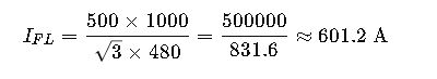
Step 2: Calculate Short-Circuit Current
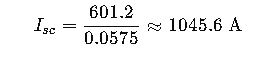
Result:
- Short-Circuit Current at the secondary terminals = 10.45 kA
This current is used to size protective devices (breakers, fuses) and to determine arc flash levels.
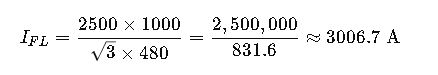
Example 2: Large 2500 kVA Transformer Feeding a Switchgear
Transformer Specifications:
- Power = 2500 kVA
- Voltage = 480 V
- Impedance = 6%
Step 1: Full Load Current
Step 2: Short-Circuit Current
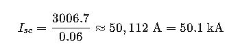
Result:
- The maximum short-circuit current could reach over 50 kA, which mandates high interrupting capacity breakers (e.g., 65kA-rated MCCBs).
Normative Reference and Practical Considerations
Normative Standards:
- IEEE C37.010 – Guide for the Application of Faulted Current Calculations
- IEEE 141 (Red Book) – Electric Power Distribution for Industrial Plants
- IEC 60909 – Short-circuit currents in three-phase AC systems
- NFPA 70 (NEC) – National Electrical Code, especially Article 450 and 240
Tip: Use IEEE Xplore or IEC Webstore to access standards.
Additional Considerations in Real Systems
- Source Contribution: Utility or generator impedance reduces fault current.
- X/R Ratio: Affects DC offset and breaker interrupting rating.
- Transformer Winding Connection: Delta vs Wye affects zero-sequence impedance.
- Motor Contribution: Motors downstream can significantly increase fault level.
- Cable Impedance: Impacts fault level at distant points.
Typical Fault Current Multipliers by Transformer Size and Impedance
| Transformer Size (kVA) | Impedance % | Fault Current Multiplier (xFLA) |
|---|---|---|
| 100 | 6 | 16.7 |
| 500 | 5.75 | 17.4 |
| 1000 | 5.75 | 17.4 |
| 2500 | 6 | 16.7 |
Advanced Case Study – Including Source and Cable Impedance
In practice, the short-circuit current at the load terminals of a transformer is affected by more than just the transformer impedance. It includes:
- Transformer impedance
- Source (utility or generator) impedance
- Cable impedance between transformer and load
Let’s demonstrate this with a real-world case.
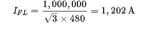
Example 3: 1000 kVA Transformer with Utility and Cable Contribution
Specifications:
- Transformer: 1000 kVA, 480 V, 5.75% impedance
- Utility fault level: 500 MVA @ 13.8 kV
- Cable: 20 m, 500 MCM copper, 3 conductors per phase
- Load voltage: 480 V
Step 1: Transformer Full Load Current
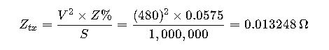
Step 2: Transformer Impedance in Ohms
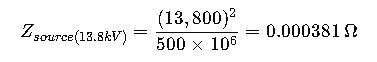
Step 3: Source Impedance (Utility)
First, convert utility fault level into impedance at the primary side:
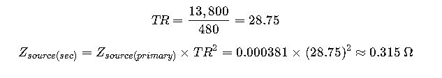
Now reflect this to the secondary side (using turns ratio squared):
Step 4: Cable Impedance (per phase)
For 3×500 MCM copper over 20 m, using standard impedance:

Step 5: Total Impedance

Step 6: Calculate Short-Circuit Current
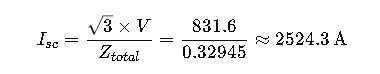
Result:
The available short-circuit current at the load terminals is approximately 2.5 kA, far less than the transformer-only fault current (~20.8 kA). This highlights the significant attenuation due to upstream and downstream impedance.
The Role of the X/R Ratio in Short-Circuit Current Calculations
The X/R ratio (reactance-to-resistance) plays a critical role in short-circuit analysis:
- Affects the asymmetrical fault current
- Influences breaker interrupting rating
- High X/R ratios lead to higher peak fault currents
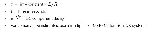
Asymmetrical Current Calculation:
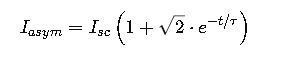
Where:
Short-Circuit Current in Delta-Wye Transformers
Delta-Wye transformers isolate zero-sequence current, so single-line-to-ground faults must consider:
- Zero-sequence impedance
- Source grounding method
- Wye secondary allows line-to-neutral fault return path
This requires:
- Positive, negative, and zero sequence impedance modeling (per IEC 60909)
- Fault type distinction (three-phase, SLG, L-L, L-L-G)
Important Real-World Design Applications
1. Breaker Sizing
- Breakers must handle the maximum symmetrical and asymmetrical current
- Example: If Isc = 50 kA, use breakers rated 65 kA or 100 kA interrupting
2. Arc Flash Analysis
- Uses Isc in incident energy and PPE category calculation
- Governed by IEEE 1584 and NFPA 70E
3. Equipment Withstand Ratings
- Switchgear, panelboards, and busbars must have adequate withstand rating
Typical Breaker and Equipment Interrupting Ratings
| Voltage Class | Breaker Type | Common Interrupting Ratings (kA) |
|---|---|---|
| 480 V | MCCB | 10, 18, 25, 35, 65, 100 |
| 480 V | Power Circuit Brkr | 25, 42, 65, 85, 100 |
| 13.8 kV | Vacuum Breaker | 16, 25, 31.5, 40 |
Always select devices with interrupting rating ≥ calculated Isc
Online Calculation Tools and Software
Free Online Calculators:
Professional Software:
- ETAP – Advanced short-circuit studies, arc flash, coordination
- SKM Power Tools
- EasyPower
- DigSILENT PowerFactory
Typical Transformer Impedance Values by Size and Type
| Transformer Rating (kVA) | Typical %Z (Dry Type) | Typical %Z (Oil-Immersed) |
|---|---|---|
| 75 | 2.5% | 3.0% |
| 150 | 3.5% | 4.0% |
| 500 | 5.75% | 5.75% |
| 1000 | 5.75% | 5.75% |
| 2500 | 6.0% | 6.0% |
| 5000 | 6.5% | 6.5% |
When Should You Perform Short-Circuit Calculations?
- Before commissioning new transformers
- During arc flash risk assessments
- Before retrofitting switchgear or breakers
- For utility interconnection studies
- When adding generators, motors, or large loads
Best Practices for Engineers
- Always consider system-wide impedance, not just transformer Z%
- Use worst-case scenarios for design and protection
- Validate all data with manufacturer datasheets
- Update calculations with system modifications
- Use professional software for coordination and selectivity