Understanding resultant force in three dimensions is essential for accurate analysis in engineering and physics.
It enables designing stable structures, analyzing mechanical systems, and controlling forces in robotics and aerospace.
Resultant Force in 3D (Vector Sum) Calculator
What are direction angles α, β, γ?
Formulas used
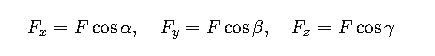
Angles input: Fx = |F|·cosα, Fy = |F|·cosβ, Fz = |F|·cosγ.
Resultant angles: αR = arccos(ΣFx/|R|), βR = arccos(ΣFy/|R|), γR = arccos(ΣFz/|R|).
Degrees or radians?
Why do I get an angles warning?
Extensive Table of Common Values for Resultant Force Components and Angles
This table summarizes typical force components (in Newtons) and angles (degrees) often encountered in engineering problems involving three-dimensional forces.
| Force Component (N) | Fx (N) | Fy (N) | Fz (N) | Magnitude F (N) | Direction Cosines (cos α, cos β, cos γ) | Angles (α, β, γ in degrees) |
|---|---|---|---|---|---|---|
| Example 1 | 50 | 75 | 100 | 134.54 | 0.372, 0.559, 0.743 | 68.2°, 56.0°, 42.1° |
| Example 2 | 120 | 160 | 80 | 213.29 | 0.562, 0.75, 0.375 | 55.7°, 41.4°, 67.9° |
| Example 3 | 0 | 100 | 100 | 141.42 | 0, 0.707, 0.707 | 90°, 45°, 45° |
| Example 4 | 30 | 40 | 0 | 50 | 0.6, 0.8, 0 | 53.13°, 36.87°, 90° |
| Example 5 | 10 | 10 | 10 | 17.32 | 0.577, 0.577, 0.577 | 54.7°, 54.7°, 54.7° |
Fundamental Formulas for Calculation of Resultant Force in Three Dimensions
1. Resultant Force Vector
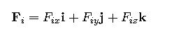
Given multiple forces F₁, F₂, …, Fₙ, each with components along the x, y, and z axes:
The resultant force FR is the vector sum:
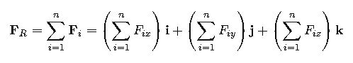
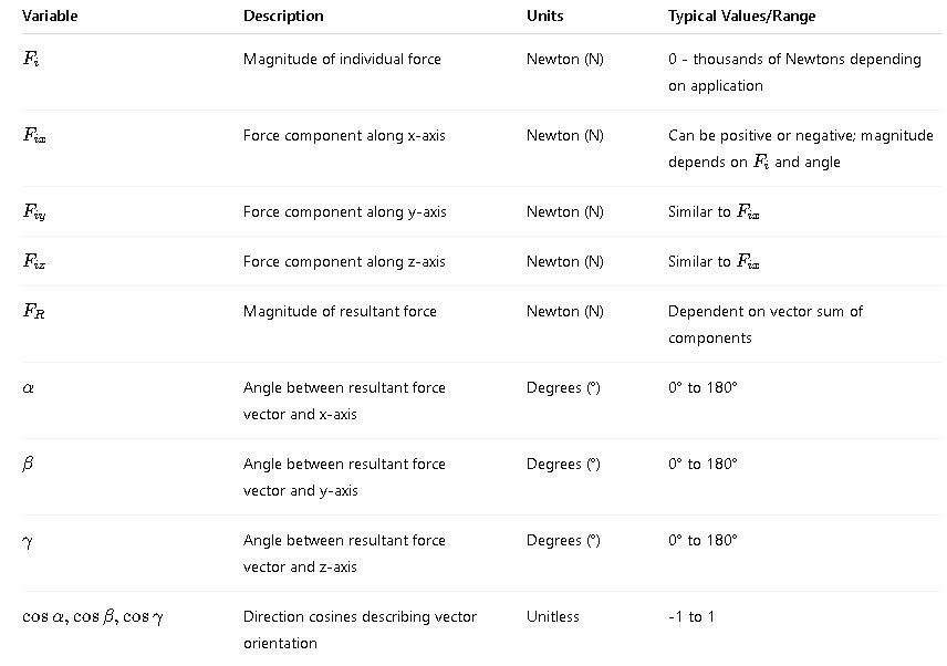
Where:
- Fix,Fiy,Fiz are the force components along the x, y, and z axes for the i-th force.
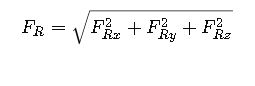
2. Magnitude of the Resultant Force
The magnitude FR of the resultant force vector FR is computed using the Euclidean norm:
Where:
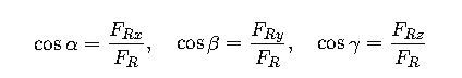
3. Direction Cosines and Angles of Resultant Force
The direction cosines cosα, cosβ, and cosγ describe the orientation of the resultant force vector relative to the coordinate axes:
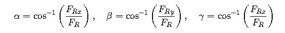
The angles α,β,γ\alpha, \beta, \gammaα,β,γ between the force vector and the coordinate axes are:
4. Component Calculation from Magnitude and Angles
Sometimes forces are given by magnitude and direction angles instead of components:
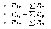
5. Equilibrium Condition in 3D
For a system in static equilibrium:
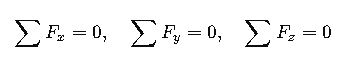
Each sum represents the algebraic sum of force components in the respective axis direction.
Explanation of Variables and Common Values
Real-World Examples of Resultant Force in Three Dimensions
Example 1: Aerospace – Calculating the Resultant Force on an Aircraft Wing
Scenario:
An aircraft wing experiences three forces due to aerodynamic pressure, gravity, and thrust vectoring.
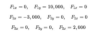
- F1 (lift force): 10,000 N acting upward along the y-axis.
- F2 (drag force): 3,000 N acting backward along the x-axis (negative x direction).
- F3 (side wind): 2,000 N acting perpendicular to the wing span along the z-axis.
Step 1: Define components
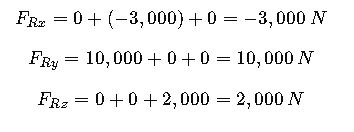
Step 2: Calculate resultant components
Step 3: Calculate magnitude

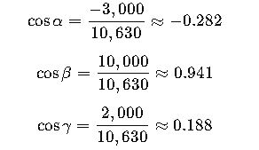
Step 4: Calculate direction cosines
Step 5: Calculate angles
Interpretation:
The resultant force has a magnitude of ~10.63 kN, directed mostly upwards along y-axis with a backward and slight sideways component.
Example 2: Civil Engineering – Forces on a Structural Joint
Scenario:
A joint in a truss structure is subjected to three forces:
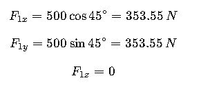
- F1: 500 N along a 45° angle from the x-axis toward the y-axis in the xy-plane (z=0).
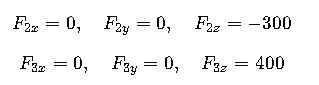
- F2: 300 N acting straight down (negative z-axis).
- F3: 400 N acting along the z-axis upward.
Step 1: Resolve F1 into components
Since F1 lies in the xy-plane at 45°:
Step 2: Other components
Step 3: Calculate resultant components
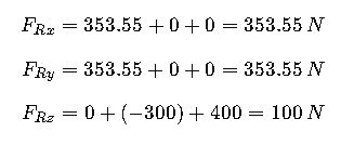
Step 4: Calculate magnitude

Step 5: Calculate direction cosines
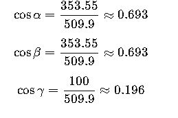
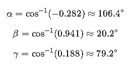
Step 6: Calculate angles
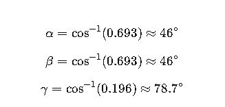
Interpretation:
The resultant force of ~510 N is mainly directed equally between x and y axes with a smaller upward component.
Additional Considerations for Advanced Calculation
Vector Representation Using Unit Vectors
In advanced mechanics, forces are often represented using unit vectors:
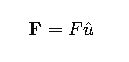
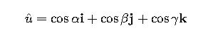
Where ![]() is the unit vector in the direction of the force:
is the unit vector in the direction of the force:
Use of Dot and Cross Products
- Dot product can be used to find the component of one force along another:
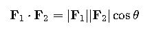
- Cross product yields a vector perpendicular to the plane containing the two forces, useful in torque calculations:
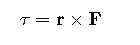
Where r is the position vector from a point of reference.
Resultant Force in Dynamic Systems
In moving bodies, resultant force is related to acceleration by Newton’s second law:
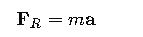
Where mmm is mass and a\mathbf{a}a acceleration vector, which must be resolved into components.
Authoritative External References
- Fundamentals of Vector Mechanics – J.L. Meriam & L.G. Kraige (Highly recommended textbook)
- NIST Engineering Statistics Handbook (Detailed on vector calculations)
- IEEE Xplore – Applied Mechanics and Force Analysis (For advanced applications)