Correctly calculating suction and discharge pressure is essential for designing efficient and safe hydraulic systems.
This guide explains formulas, values, examples, and applications following engineering best practices and industrial standards.
Pump Suction & Discharge Pressure Calculator
Common Values in Pump Suction and Discharge Pressure Calculations
Below is a detailed table summarizing commonly encountered values in industrial and municipal applications, including suction pressure, discharge pressure, pump head, fluid temperature, and more. These values are typically observed in centrifugal and positive displacement pumps.
Table 1: Common Parameters for Pump Suction and Discharge Calculations
| Fluid Type | Suction Pressure (psi) | Discharge Pressure (psi) | Flow Rate (GPM) | Pump Head (ft) | Fluid Temp (°C) | Viscosity (cP) | Elevation (ft) |
|---|---|---|---|---|---|---|---|
| Water (cold, 20°C) | 10 – 20 | 40 – 80 | 50 – 1000 | 50 – 200 | 20 | 1 | 0 – 500 |
| Hot Water (80°C) | 5 – 15 | 60 – 120 | 100 – 800 | 80 – 250 | 80 | 1 | 0 – 300 |
| Diesel Fuel | 5 – 10 | 30 – 60 | 50 – 300 | 30 – 100 | 20 | 3 | 0 – 200 |
| Crude Oil (heavy) | 0 – 5 | 80 – 200 | 20 – 200 | 100 – 300 | 60 | 100 – 500 | 0 – 100 |
| Seawater | 10 – 20 | 50 – 100 | 100 – 1200 | 60 – 180 | 25 | 1 | 0 – 100 |
| Chemical Slurry | 0 – 10 | 100 – 300 | 30 – 150 | 100 – 350 | 50 | 300 – 1000 | 0 – 50 |
| Air (compressors) | 15 (atm) | 100 – 150 | – | – | 25 | – | 0 |
Note: These values are illustrative averages and should be verified against project-specific conditions and fluid properties.
Detailed Formulas for Pump Suction and Discharge Pressure
To perform accurate calculations, it is essential to understand the formulas governing suction and discharge pressures. These formulas depend on factors such as static head, friction losses, fluid properties, and velocity head.
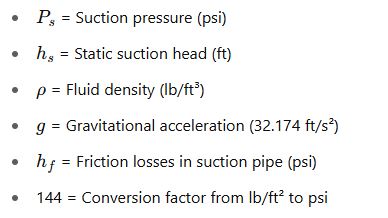
Key Formula 1: Suction Pressure (Ps)
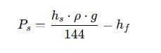
Where:
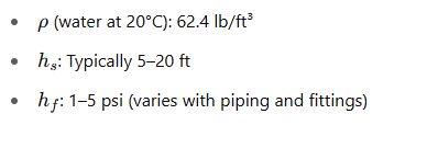
Common Values:
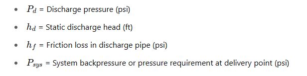
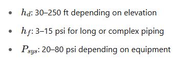
Key Formula 2: Discharge Pressure (Pd)
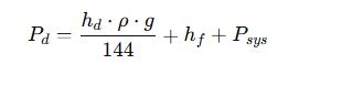
Where:
Common Values:
Key Formula 3: Total Dynamic Head (TDH)

This is critical in selecting pumps, as it represents the total energy a pump must impart.
Key Formula 4: Net Positive Suction Head Available (NPSHa)
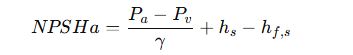
Where:
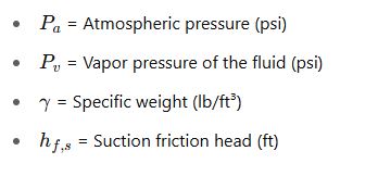
This formula ensures cavitation does not occur. Compare NPSHa to NPSHr (from manufacturer).
Key Formula 5: Pressure from Head
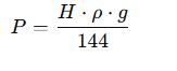
Used to convert head into pressure.
Real-World Example 1: Pumping Cold Water in an Industrial Facility
Problem Statement:
An industrial facility needs to pump cold water from a ground tank to a rooftop tank 40 ft above. The suction pipe length is 20 ft, and the discharge pipe is 60 ft. Suction static head is 5 ft, and discharge head is 40 ft. Assume:
- Water density = 62.4 lb/ft³
- Suction friction loss = 2 psi
- Discharge friction loss = 5 psi
- Atmospheric pressure = 14.7 psi
- Vapor pressure = 0.3 psi
Step-by-Step Calculation:
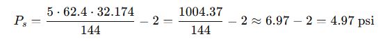
1. Suction Pressure:
2. Discharge Pressure:

3. TDH:

4. NPSHa:

Result:
- Suction Pressure: 4.97 psi
- Discharge Pressure: 60.68 psi
- NPSHa: 10.42 ft
- Check NPSHa > NPSHr (manufacturer must confirm)
Real-World Example 2: Crude Oil Transfer in a Refinery
Problem Statement:
A refinery needs to transfer heavy crude oil from a storage tank to a processing unit. The system has the following parameters:
- Fluid: Heavy crude oil (viscosity: 250 cP, density: 52 lb/ft³)
- Suction lift: 3 ft (pump is above the fluid level)
- Suction pipe length: 25 ft, friction loss: 3 psi
- Discharge static head: 60 ft
- Discharge pipe friction loss: 8 psi
- Atmospheric pressure: 14.7 psi
- Vapor pressure: 0.2 psi
Step-by-Step Calculation:
1. Suction Pressure (Lift Configuration)

Note: A negative suction pressure indicates vacuum conditions, which are typical in lift situations.
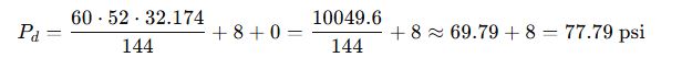
2. Discharge Pressure:
3. Total Dynamic Head (TDH):

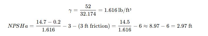
4. NPSHa:
Result:
- Suction Pressure: -6.49 psi
- Discharge Pressure: 77.79 psi
- NPSHa: 2.97 ft → must be higher than NPSHr (e.g. 4 ft), otherwise risk of cavitation.
Action:
- This system may experience cavitation. Recommend lowering pump elevation or adding a booster pump.
Common Errors in Pump Pressure Calculations
Understanding common mistakes helps avoid costly system failures.
1. Ignoring Suction Lift or Head
- Overlooking vertical differences leads to miscalculating suction pressure and potential cavitation.
2. Misestimating Friction Losses
- Using generic values instead of computing losses from actual pipe length, diameter, and fittings.
3. Not Considering NPSH
- Failing to compare NPSHa with NPSHr from the pump datasheet leads to cavitation and damage.
4. Incorrect Unit Conversions
- Mixing up psi, ft, meters, and bar is common. Always double-check conversions.
5. Disregarding Fluid Properties
- Viscosity and density significantly affect pressure drops and required head.
Design Recommendations
1. Optimize Suction Conditions
- Keep pumps below fluid level (positive suction head) when possible.
- Use larger diameter suction pipes to reduce losses.
2. Reduce Friction Losses
- Use long-radius elbows, fewer fittings, and smooth pipe materials.
- Perform detailed friction loss calculations (e.g. using Hazen-Williams or Darcy-Weisbach).
3. Maintain Adequate NPSHa
- Ensure atmospheric pressure, fluid temperature, and elevation keep NPSHa > NPSHr.
4. Use Variable Frequency Drives (VFDs)
- They allow pressure control by adjusting speed, enhancing energy efficiency and system response.
5. Validate with Pump Manufacturer
- Always compare calculated pressures and heads with pump curves and specifications.
Authoritative External References
For further reading and validation of engineering calculations, consult these respected sources:
- Hydraulic Institute Standards
- Pump Handbook by McGraw-Hill
- Crane Technical Paper No. 410 – Flow of Fluids
- Engineering Toolbox – Pump Systems
- Cameron Hydraulic Data
Additional Useful Tables
Table 2: Approximate Friction Loss per 100 ft of Pipe for Water (Schedule 40)
| Pipe Diameter (in) | 50 GPM | 100 GPM | 200 GPM | 500 GPM |
|---|---|---|---|---|
| 1″ | 16.6 | – | – | – |
| 2″ | 1.6 | 5.5 | – | – |
| 4″ | 0.2 | 0.5 | 2.2 | – |
| 6″ | 0.06 | 0.18 | 0.6 | 2.8 |
| 8″ | 0.02 | 0.06 | 0.2 | 1.0 |
Values in psi, water at 20°C.
Table 3: NPSH Required by Typical Pumps (manufacturer estimates)
| Pump Type | Flow Rate (GPM) | NPSHr (ft) |
|---|---|---|
| End Suction Centrifugal | 100 | 6 |
| Vertical Inline | 250 | 9 |
| Split-Case Double Suction | 500 | 10 |
| Positive Displacement | 100 | 4 |
| Slurry Pump | 150 | 12 |
Final Thoughts
Calculating pump suction and discharge pressure is a critical engineering task requiring thorough analysis of head, pressure drops, fluid properties, and system configuration. Accuracy in these calculations leads to safer operations, optimized energy use, and extended equipment lifespan.
For systems involving high viscosity, variable elevations, or complex piping, use simulation software like:
- AFT Fathom – for incompressible pipe flow
- PipeFlow Expert
- Bentley Hammer – for transient and surge analysis
Always combine theoretical calculations with practical field data, and validate with pump manufacturers for reliable and safe system design.