Transformers are vital in power systems. Accurate current calculation ensures safe, efficient, and compliant electrical designs.
Correct current values guide protective device selection, cable sizing, and maintain power network integrity in all conditions.
Transformer Current Calculator
Extensive Tables of Common Transformer Current Values
The following tables provide typical values of primary and secondary currents for common transformer ratings at different voltage levels in both single-phase and three-phase configurations.
Table 1: Three-Phase Transformer Current Values (400 V / 11 kV)
| Transformer Power (kVA) | Primary Voltage (V) | Primary Current (A) | Secondary Voltage (V) | Secondary Current (A) |
|---|---|---|---|---|
| 50 | 11000 | 2.62 | 400 | 72.16 |
| 100 | 11000 | 5.25 | 400 | 144.34 |
| 200 | 11000 | 10.49 | 400 | 288.68 |
| 315 | 11000 | 16.52 | 400 | 454.61 |
| 500 | 11000 | 26.24 | 400 | 721.69 |
| 800 | 11000 | 41.99 | 400 | 1154.7 |
| 1000 | 11000 | 52.48 | 400 | 1443.4 |
| 1600 | 11000 | 83.96 | 400 | 2309.4 |
| 2000 | 11000 | 104.95 | 400 | 2886.8 |
Table 2: Single-Phase Transformer Current Values (240 V / 11 kV)
| Transformer Power (kVA) | Primary Voltage (V) | Primary Current (A) | Secondary Voltage (V) | Secondary Current (A) |
|---|---|---|---|---|
| 10 | 11000 | 0.91 | 240 | 41.67 |
| 25 | 11000 | 2.27 | 240 | 104.17 |
| 50 | 11000 | 4.55 | 240 | 208.33 |
| 100 | 11000 | 9.09 | 240 | 416.67 |
| 160 | 11000 | 14.54 | 240 | 666.67 |
| 250 | 11000 | 22.73 | 240 | 1041.67 |
These tables assume ideal conditions (100% efficiency). Real-world applications may introduce a correction factor for losses and impedance.
Formulas for Primary and Secondary Current Calculation
Transformer current calculation relies on basic power and voltage relationships, which vary between single-phase and three-phase systems.
1. Single-Phase Transformer Current Formula
Primary Current:

Secondary Current:

2. Three-Phase Transformer Current Formula
Primary Current:

Secondary Current:

Detailed Explanation of Variables
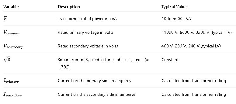
For accurate results, efficiency and power factor may be incorporated, particularly in systems where reactive power is significant.
Extended Formulas with Efficiency and Power Factor (Advanced)
For real-world transformers, losses and phase angle need to be considered.
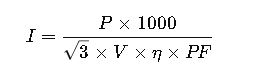
Where:
- η= Efficiency (typically 0.97 to 0.99)
- PF= Power factor (0.8 to 1)
These are used in protection and energy audit contexts.
Real-World Application Examples
Example 1: Industrial Transformer – Step-Down Application
Scenario:
A manufacturing facility uses a 1000 kVA, 11 kV / 400 V three-phase transformer to supply machinery.
Objective:
Calculate the primary and secondary currents.
Given:
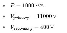
Solution:
Primary Current:

Secondary Current:

These values guide the selection of protection relays, CTs, and conductors. For example, a 1600 A MCCB or ACB with adjustable thermal protection would be used on the secondary.
Example 2: Utility Distribution Transformer – Pole-Mounted System
Scenario:
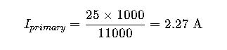
A utility company installs a single-phase 25 kVA transformer (11 kV / 240 V) in a rural area.
Objective:
Calculate primary and secondary currents for cable selection.
Given:
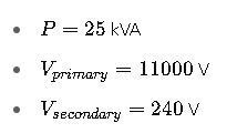
Solution:
Primary Current:
Secondary Current:

Cables rated for 125 A would be chosen on the LV side, and an 11 kV line drop calculation would be performed to validate the MV connection.
Normative and Regulatory Considerations
When calculating transformer currents and sizing electrical components, adherence to international and regional standards is crucial. The following standards provide technical criteria, tolerances, and safety considerations for transformer design and operation:
Key Standards:
- IEC 60076 – Power Transformers (International Electrotechnical Commission):
Defines rating, testing, and performance requirements for power transformers. - IEEE C57 – Distribution and Power Transformers (Institute of Electrical and Electronics Engineers):
U.S.-based transformer standardization covering load tap changers, insulation, and testing. - NFPA 70 (NEC) – National Electrical Code (United States):
Specifies conductor sizing, protection, and grounding practices. - IEC 60364 – Electrical Installations for Buildings:
Guides protective device coordination and conductor dimensioning. - NEMA ST 20 – Dry-Type Transformers for General Applications:
Focuses on efficiency and safe operation of dry-type transformers in commercial and industrial settings.
For detailed transformer sizing and protections, consult:
IEC 60076-1 standard (external link)
Common Mistakes and Practical Considerations
Even experienced engineers may overlook key details in transformer current calculations. Below are typical pitfalls and how to avoid them:
1. Ignoring Power Factor or Efficiency
- Real-world transformers operate below 100% efficiency. Neglecting these leads to underestimating actual current draw.
- Always include efficiency (η) and power factor (PF) in critical applications.
2. Misapplying Formulas Between Phases
- Use the correct formula: single-phase vs. three-phase.
- Applying the
 factor to single-phase systems yields wrong current values.
3. Rounding Errors
- For small transformers, 0.1 A matters in protection device selection.
- Use accurate values and maintain at least 3 decimal places during intermediate steps.
4. Skipping Load Growth Estimations
- In industrial settings, future expansions must be considered.
- It’s good practice to apply a 20% load growth margin for secondary currents.
Cable and Protection Implications of Transformer Currents
The results of current calculations directly impact:
1. Conductor Sizing
- NEC Table 310.16 or IEC 60364-5-52 must be used to size cables.
- Consider thermal limits, insulation type, installation conditions, and ambient temperature.
2. Protection Devices
- Protection must match both the primary and secondary currents:
- Fuses
- Circuit Breakers (MCCB/ACB)
- Relays with CTs
A good practice is to size protection at 125% of full-load current for continuous duty.
Example 3: Hospital Backup Transformer – 1600 kVA
Scenario:
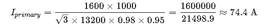
A 1600 kVA, 13.2 kV / 480 V transformer supplies emergency power to a hospital complex.
Objective:
Calculate primary and secondary currents, and specify protection and cable requirements.
Given:
- Power: 1600 kVA
- Primary voltage: 13.2 kV
- Secondary voltage: 480 V
- Efficiency: 98%
- Power Factor: 0.95
Solution:
Primary Current:
Secondary Current:

Cable Selection:
- Primary: 3C 150 mm² XLPE, based on 90°C insulation rating.
- Secondary: Parallel 3 x 4C 400 mm² XLPE + neutral.
Protection:
- Primary Side: 100 A vacuum circuit breaker with 75/5 CTs.
- Secondary Side: 2500 A ACB with adjustable long-time trip.
Transformer Current Calculator Integration (Web Tool Use)
For faster estimations, many professionals use online calculators.
Features of a Good Transformer Current Calculator:
- Supports both single and three-phase
- Efficiency and PF inputs
- Handles voltage ranges up to 33 kV
- Printable reports
- IEC and IEEE compliance
Example tool:
ABB Transformer Sizing Tool
Checklist for Transformer Current Calculation
| Task | Status |
|---|---|
| Identify transformer rating (kVA) | ✅ |
| Determine primary and secondary voltages | ✅ |
| Choose correct phase configuration | ✅ |
| Apply correct formula | ✅ |
| Factor in efficiency and PF | ✅ |
| Select conductors and protections | ✅ |
| Validate with standards (IEC/IEEE) | ✅ |
FAQ – Transformer Current Calculation
1. What is the difference between primary and secondary current?
Primary current flows on the high-voltage side, secondary on the low-voltage side. They are inversely proportional to voltage if power is constant.
2. Does the current change with load?
Yes. These calculations assume full load. Partial loads will draw proportionally lower current.
3. Why use in three-phase calculations?
It converts line-to-line voltage to per-phase voltage, needed for total power computation in a balanced system.