The bending radius of electrical conduits is essential for ensuring structural integrity and safe installations. Accurate calculation prevents damage to cables and maintains conduit performance during and after installation.
Minimum Bending Radius Calculator for Electrical Conduits
Extensive Tables of Common Minimum Bending Radius Values for Electrical Conduits
The minimum bending radius depends primarily on the conduit material, diameter, and sometimes the type of cables inside. Various standards and manufacturers specify these values, often expressed as multiples of conduit diameter (D) or cable diameter.
Below are extensive tables summarizing typical minimum bending radii for common conduit materials and sizes, based on industry standards like NEC (National Electrical Code), IEC 61386, and manufacturer recommendations.
Table 1: Minimum Bending Radius for Rigid Metal Conduits (RMC) and Intermediate Metal Conduits (IMC)
| Conduit Size (inches) | Outer Diameter (inches) | Minimum Bending Radius (inches) | Minimum Bending Radius (mm) | Radius Factor (× OD) |
|---|---|---|---|---|
| 1/2 | 0.84 | 12 | 305 | 14.3 |
| 3/4 | 1.05 | 15 | 381 | 14.3 |
| 1 | 1.32 | 18 | 457 | 13.6 |
| 1 1/4 | 1.66 | 24 | 610 | 14.5 |
| 1 1/2 | 1.90 | 27 | 686 | 14.2 |
| 2 | 2.38 | 36 | 914 | 15.1 |
| 2 1/2 | 2.87 | 42 | 1067 | 14.6 |
| 3 | 3.50 | 54 | 1372 | 15.4 |
| 3 1/2 | 4.00 | 60 | 1524 | 15 |
| 4 | 4.50 | 72 | 1829 | 16 |
Table 2: Minimum Bending Radius for Electrical Metallic Tubing (EMT)
| Conduit Size (inches) | Outer Diameter (inches) | Minimum Bending Radius (inches) | Minimum Bending Radius (mm) | Radius Factor (× OD) |
|---|---|---|---|---|
| 1/2 | 0.70 | 8 | 203 | 11.4 |
| 3/4 | 0.88 | 10 | 254 | 11.4 |
| 1 | 1.16 | 12 | 305 | 10.3 |
| 1 1/4 | 1.38 | 16 | 406 | 11.6 |
| 1 1/2 | 1.61 | 18 | 457 | 11.2 |
| 2 | 2.13 | 24 | 610 | 11.3 |
| 2 1/2 | 2.57 | 30 | 762 | 11.7 |
| 3 | 3.13 | 36 | 914 | 11.5 |
| 3 1/2 | 3.50 | 42 | 1067 | 12 |
| 4 | 4.16 | 48 | 1219 | 11.5 |
Table 3: Minimum Bending Radius for PVC Electrical Conduits (Schedule 40 & 80)
| Conduit Size (inches) | Outer Diameter (inches) | Min. Bending Radius (inches) | Min. Bending Radius (mm) | Radius Factor (× OD) |
|---|---|---|---|---|
| 1/2 | 0.84 | 12 | 305 | 14.3 |
| 3/4 | 1.05 | 15 | 381 | 14.3 |
| 1 | 1.32 | 18 | 457 | 13.6 |
| 1 1/4 | 1.66 | 24 | 610 | 14.5 |
| 1 1/2 | 1.90 | 27 | 686 | 14.2 |
| 2 | 2.38 | 36 | 914 | 15.1 |
| 2 1/2 | 2.87 | 42 | 1067 | 14.6 |
| 3 | 3.50 | 54 | 1372 | 15.4 |
| 3 1/2 | 4.00 | 60 | 1524 | 15 |
| 4 | 4.50 | 72 | 1829 | 16 |
Formulas for Calculating Minimum Bending Radius for Electrical Conduits
Calculation of minimum bending radius depends on several factors, such as conduit diameter, cable type, conduit material, and installation requirements. The bending radius is typically related to conduit outer diameter or cable diameter through empirical or standard-based formulas.
Basic Formula for Minimum Bending Radius Based on Conduit Diameter

Where:
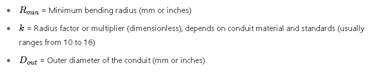
Explanation:
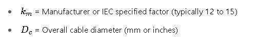
- The factor k accounts for the flexibility of the conduit material and the permissible deformation during bending without damage.
- Typical k values from standards are:
- Rigid Metal Conduits (RMC): 14–16
- Electrical Metallic Tubing (EMT): 10–12
- PVC Conduits: 14–16
Formula for Minimum Bending Radius Considering Cable Properties
For conduit filled with cables, the cable manufacturer’s minimum bending radius must also be considered to avoid damage.

Where:
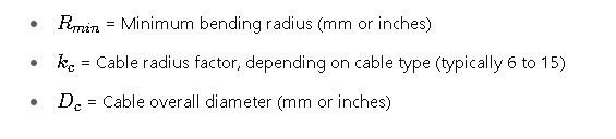
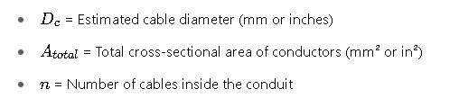
Formula for Calculating Cable Diameter from Conduit Fill
If cable diameter is not known, it can be estimated based on conduit fill percentage and conductor size:
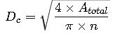
Where:
Formula for Minimum Bend Radius for Multi-conductor Cables (IEC 60228)
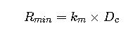
Where
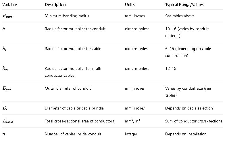
Detailed Explanation of Variables and Common Values
Real-World Examples of Minimum Bending Radius Calculation
Example 1: Determining Minimum Bending Radius for a 1-Inch Rigid Metal Conduit (RMC)
Problem:
An electrical engineer needs to install a 1-inch Rigid Metal Conduit (RMC) in a commercial building. What is the minimum bending radius to comply with NEC guidelines?
Solution:
From Table 1:

Calculate minimum bending radius:

Interpretation:
The conduit should be bent with a radius no less than 18.5 inches to prevent damage and maintain installation standards.
Example 2: Minimum Bending Radius for PVC Conduit with Multi-core Cable
Problem:
A 2-inch PVC Schedule 40 conduit houses a multi-core cable with a diameter of 40 mm. The cable manufacturer specifies a minimum bend radius factor of 15.
Find the minimum bending radius to ensure cable integrity inside the conduit.
Solution:
- From Table 3, the minimum bending radius based on conduit:
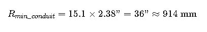
- Based on cable:

Decision:
- The larger radius controls. Here, 914 mm (conduit radius) > 600 mm (cable radius)
- Therefore, the minimum bending radius for the installation must be at least 914 mm.
Additional Considerations and In-Depth Analysis
Influence of Temperature and Material Properties
- PVC and other plastic conduits become more flexible at elevated temperatures, which may reduce the effective bending radius but risk permanent deformation.
- Metal conduits maintain structural rigidity but require larger bending radii to avoid kinks.
Effects of Conduit Fill and Cable Type
- Higher conduit fill reduces flexibility.
- Larger or armored cables necessitate larger bending radii.
- NEC 300.34 and IEC 61386 provide fill tables and recommendations.
Installation Best Practices
- Use conduit bending tools matched to the conduit type and diameter.
- Avoid sharp bends exceeding the minimum radius.
- For multiple bends, maintain adequate spacing between bends to avoid cumulative stress.
Regulatory and Standard References
- NEC (NFPA 70) Article 352 — for Rigid PVC conduits
- NEC Article 344 — for Rigid Metal Conduit (RMC)
- IEC 61386 — Conduits for electrical installations
- Manufacturer Datasheets — for cable bending radius
Summary of Critical Parameters
| Parameter | Importance | Typical Impact |
|---|---|---|
| Minimum bending radius | Prevent conduit damage and maintain cable integrity | Avoids kinking, conductor damage |
| Conduit diameter | Base dimension for radius calculation | Larger diameter requires larger radius |
| Material flexibility | Influences radius factor kkk | Flexible materials have smaller radius |
| Cable type & diameter | Critical for cable bending radius | Bigger cables need larger radius |
| Installation conditions | Temperature, fill percentage, and mechanical stress | Affect radius and installation approach |
Recommended External Authoritative Resources
- National Electrical Code (NEC): NFPA 70
- IEC 61386 Standard: IEC Website
- IEEE Guide for Electrical Conduit Installation: IEEE Xplore
- Cable Manufacturer Installation Guides: Consult specific manufacturer datasheets (e.g., Southwire, Prysmian)