Proper sizing of fuses and circuit breakers ensures electrical safety, equipment protection, and NEC compliance. Incorrect sizing causes nuisance trips or unsafe conditions by failing to clear faults properly.
Fuse and Circuit Breaker Sizing (NEC)
Extensive Tables of Common Fuse and Circuit Breaker Sizing Values (NEC-Based)
The NEC provides guidelines to determine overcurrent protective device (OCPD) ratings based on conductor ampacity, load characteristics, and system type. Below are detailed tables of commonly used OCPD sizes, typical conductor ampacities, and associated load types.
| Conductor AWG / Size | Copper Conductor Ampacity (NEC Table 310.16, 75°C) | Typical OCPD Size (Amps) | Common Application |
|---|---|---|---|
| 14 AWG | 20 A | 15 A, 20 A | Lighting circuits, small branch circuits |
| 12 AWG | 25 A | 20 A, 25 A | General branch circuits |
| 10 AWG | 35 A | 30 A, 35 A | Branch circuits for small motors or appliances |
| 8 AWG | 50 A | 40 A, 50 A | Small motors, subpanels |
| 6 AWG | 65 A | 60 A, 70 A | Larger motors, feeders |
| 4 AWG | 85 A | 70 A, 90 A | Feeders, HVAC units |
| 3 AWG | 100 A | 90 A, 100 A | Main feeders |
| 2 AWG | 115 A | 100 A, 125 A | Feeders and branch circuits |
| 1 AWG | 130 A | 125 A, 150 A | Larger feeders, motor circuits |
| 1/0 AWG | 150 A | 150 A, 175 A | Large motors, feeders |
| 2/0 AWG | 175 A | 175 A, 200 A | Industrial feeders |
| 3/0 AWG | 200 A | 200 A, 225 A | Larger industrial feeders |
| 4/0 AWG | 230 A | 225 A, 250 A | Industrial power circuits |
Typical Fuse and Breaker Ratings for Motor Loads (NEC Article 430)
| Motor HP | Full Load Current (FLC) (Amps) | Typical OCPD Rating (Amps) | NEC Reference |
|---|---|---|---|
| 1/2 HP | 4.8 | 10 – 15 | NEC 430.52 |
| 1 HP | 7.2 | 15 – 20 | NEC 430.52 |
| 3 HP | 17.0 | 25 – 35 | NEC 430.52 |
| 5 HP | 28.0 | 40 – 50 | NEC 430.52 |
| 7.5 HP | 34.0 | 45 – 60 | NEC 430.52 |
| 10 HP | 45.0 | 60 – 70 | NEC 430.52 |
| 15 HP | 65.0 | 90 – 100 | NEC 430.52 |
| 20 HP | 83.0 | 100 – 125 | NEC 430.52 |
| 25 HP | 99.0 | 125 – 150 | NEC 430.52 |
Common Standard Fuse Ratings (Ampere Classes)
| Fuse Type | Ampere Rating (A) | Common Applications |
|---|---|---|
| Class RK5 Fuse | 1, 2, 3, 4, 5, 6, 8, 10, 12, 15, 20, 25, 30, 35, 40, 45, 50, 60, 70, 80, 90, 100, 110, 125, 150, 175, 200 | Industrial, motor protection, feeders |
| Class H Fuse | 1, 2, 3, 4, 5, 6, 8, 10, 12, 15, 20, 25, 30, 35, 40, 45, 50, 60, 70, 80, 90, 100 | Lighting, residential, small motors |
| Cartridge Fuse | 15, 20, 25, 30, 35, 40, 45, 50, 60, 70, 80, 90, 100 | General purpose, residential |
Fundamental Formulas for Fuse and Circuit Breaker Sizing (NEC)
Sizing fuses and circuit breakers requires understanding the key formulas that relate load currents, conductor ampacity, and device ratings. Below are the main formulas and explanations for each variable used in sizing calculations.
1. Basic Load Current Calculation
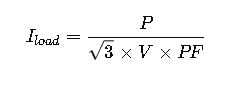
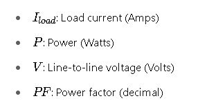
Explanation: For three-phase loads, current is calculated by dividing power by the product of line voltage and power factor, normalized by ![]() For single-phase, remove
For single-phase, remove ![]()
2. Maximum OCPD Rating for Continuous Loads
Per NEC 240.6(A) and 210.20(A):
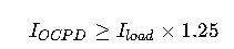
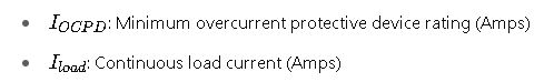
Explanation: The OCPD must be sized to at least 125% of continuous load current to prevent nuisance tripping.
3. Conductor Ampacity Check


Explanation: The conductor must have an ampacity equal to or exceeding the OCPD rating to safely handle the expected load current.
4. Motor Overcurrent Device Sizing (NEC Article 430.52)
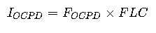
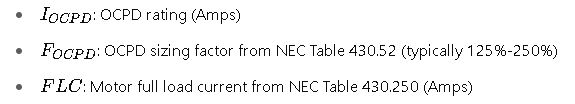
Explanation: Motor protection devices are sized as a percentage multiplier of the motor’s full load current.
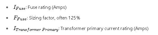
5. Fuse Sizing for Transformer Primary Protection (NEC 450.3(B))

6. Breaker Interrupting Rating Check
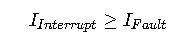

Explanation: The device must be capable of interrupting the maximum available fault current at its installation point.
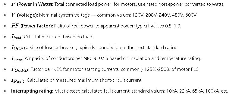
Detailed Explanation of Variables and Common Values
Real-World Application Examples
Example 1: Sizing a Circuit Breaker and Conductor for a 20 kW Three-Phase Motor Load at 480V
Given:
- Motor Power P=20,000W (20 kW)
- Voltage V=480V (three-phase)
- Power Factor PF=0.9 (typical motor)
- Continuous Load: Yes (motor runs for >3 hours)
- Motor full load current from NEC Table 430.250: Approx. 28.8 A (for 20 kW, 480 V, 60 Hz)
- Select breaker size and conductor.
Step 1: Calculate Full Load Current Iload
Using:
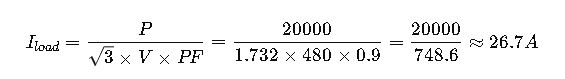
Step 2: Calculate Minimum OCPD Rating
Using motor multiplier from NEC 430.52, typically 125% for motor starters:
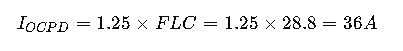
Choose the next standard breaker size: 40 A.
Step 3: Select Conductor Ampacity
Conductor ampacity must be ≥IOCPD=40A
From NEC 310.16:
- 8 AWG copper conductor ampacity at 75°C = 50 A → adequate.
- Choose 8 AWG copper conductor.
Step 4: Verify Interrupting Rating
Assuming fault current available at panel is 10kA:
- Select breaker with interrupting rating ≥\geq≥ 10kA.
Example 2: Fuse Sizing for Transformer Primary Protection
Given:
- Transformer rating: 75 kVA
- Primary voltage: 480 V
- Transformer primary current:

Step 1: Calculate Fuse Size
Using NEC 450.3(B) sizing factor of 125%:
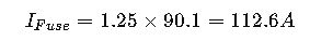
Choose standard fuse size: 125 A Class RK5 fuse.
Step 2: Select Secondary Protection
- Secondary rated at 208 V, 208 V side rated current:

Choose fuse or breaker accordingly on the secondary side.
Additional Considerations for Accurate Sizing
- Ambient temperature correction: Per NEC 310.15(B)(2)(a), conductors must be derated for high temperatures.
- Conductor bundling and conduit fill: Affects ampacity; apply adjustment factors.
- Motor starting currents: Use time-delay fuses or breakers to allow inrush currents.
- Selective coordination: Consider coordination between upstream and downstream devices to isolate faults.
- Voltage drop: Ensure conductors are sized to limit voltage drop (max 3-5%).
References and Authoritative Resources
- National Electrical Code (NEC) 2023 Edition — Official code for electrical installations.
- NEC Article 240: Overcurrent Protection — Details on fuse and breaker sizing.
- NEC Article 430: Motors, Motor Circuits, and Controllers — Motor-specific protection requirements.
- NEC Table 310.16: Conductor Ampacities — Ampacity of conductors.
- Eaton Corporation Fuse and Circuit Breaker Sizing Guide — Practical application examples.
- Schneider Electric Technical Documentation — Overcurrent device selection