Braking torque is a fundamental engineering parameter, defining stopping power and linking vehicle dynamics to hardware. Engineers calculate braking torque precisely to size discs, drums, calipers, actuators across vehicles and machinery.
Braking Torque Calculator — Compute Required Brake Torque (N·m / lbf·ft)
When should I use ‘from force’ vs ‘from deceleration’?
Use ‘from force’ when you know braking force at the tyre contact. Use ‘from deceleration’ to compute torque required to decelerate a vehicle with a known mass and wheel radius.
Formulas used
Direct:
From deceleration (neglecting driveline losses): total braking force required =
With rotational inertia (optional): add rotational torque:
T = F · r (Torque = force × radius).From deceleration (neglecting driveline losses): total braking force required =
F_total = m · a → torque per wheel = T = (m · a · r) / n where n = number of braked wheels.With rotational inertia (optional): add rotational torque:
T_inertia = I_wheel · α with α = a / r. Final per-wheel torque = T = (m·a·r)/n + T_inertia.Why results differ from brake manufacturer specs?
Manufacturers often quote nominal friction torque, pad area, hydraulic amplification and test conditions. Use this calculator as an engineering estimate and include safety factors and mechanical efficiency.
Comprehensive Tables of Common Braking Torque Values
The following tables summarize common values used in braking torque calculations. These ranges are drawn from industrial design standards, research papers, and real-world engineering practices.
Table 1. Typical Friction Coefficients (μ) in Braking Systems
| Material Pair (Pad/Shoe vs. Disc/Drum) | Static μ | Dynamic μ | Common Range in Practice |
|---|---|---|---|
| Organic pad vs. cast iron disc | 0.30 | 0.25 | 0.20 – 0.35 |
| Semi-metallic pad vs. cast iron disc | 0.40 | 0.35 | 0.30 – 0.45 |
| Ceramic pad vs. steel disc | 0.38 | 0.34 | 0.28 – 0.42 |
| Drum brake shoe vs. cast iron drum | 0.35 | 0.30 | 0.25 – 0.40 |
| Industrial brake linings (woven) | 0.45 | 0.40 | 0.35 – 0.50 |
| Wind turbine disc vs. composite pad | 0.42 | 0.36 | 0.32 – 0.48 |
Table 2. Common Brake Disc Radii and Effective Radii (r)
| Vehicle Type | Disc Outer Radius (mm) | Effective Radius (mm) | Notes |
|---|---|---|---|
| Passenger car (compact) | 140 – 160 | 120 – 140 | Front axle |
| Passenger car (SUV) | 160 – 180 | 140 – 160 | Larger load |
| Light truck | 180 – 220 | 160 – 200 | Heavier wheels |
| Heavy truck | 250 – 350 | 220 – 300 | Ventilated discs |
| Rail vehicle | 300 – 400 | 260 – 360 | Higher inertia |
| Wind turbine brake | 500 – 1000 | 400 – 900 | Slow but high torque |
Table 3. Typical Braking Forces (Normal Force F) per Wheel
| Vehicle / Application | Brake Type | Normal Force (N) per Pad/Shoe |
|---|---|---|
| Compact car | Hydraulic disc | 8,000 – 12,000 |
| SUV / Pickup | Hydraulic disc | 12,000 – 18,000 |
| Heavy truck | Pneumatic disc/drum | 20,000 – 35,000 |
| High-speed train | Disc brake | 40,000 – 60,000 |
| Wind turbine yaw brake | Hydraulic disc | 100,000 – 200,000 |
| Industrial crane brake | Drum brake | 50,000 – 100,000 |
Table 4. Approximate Braking Torque Values in Practice
| Application | Typical Torque (Nm) per Wheel |
|---|---|
| Compact passenger car | 800 – 1,200 |
| SUV / pickup truck | 1,200 – 2,000 |
| Heavy truck (axle) | 8,000 – 12,000 |
| Rail bogie brake | 15,000 – 25,000 |
| Wind turbine brake | 100,000 – 300,000 |
| Elevator brake | 1,000 – 3,000 |
Braking Torque Formulas and Detailed Variable Explanations
The core braking torque equation is derived from the relationship between frictional force and radius of application:
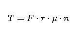
Where:
- T = braking torque (Nm)
- F = normal (clamping or shoe) force applied on the brake pad/disc (N)
- r = effective radius of braking (m)
- μ = coefficient of friction (dimensionless, typically 0.25–0.45 for brakes)
- n = number of friction interfaces (2 for disc brakes, sometimes more for multi-disc brakes)
Extended Formulas
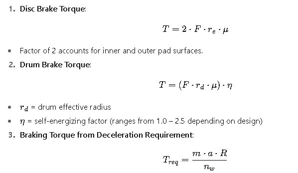
Where:
- m= vehicle mass (kg)
- a = desired deceleration (m/s², often 0.8–1.0 g for emergency braking)
- R= dynamic wheel radius (m)
- nw= number of wheels providing braking force
Typical Ranges of Variables
- Coefficient of friction (μ): 0.20 – 0.50 (see Table 1)
- Effective radius (r): 0.12 – 0.90 m depending on vehicle size
- Clamping force (F): 8,000 – 200,000 N depending on application
- Vehicle deceleration target: 3–10 m/s² (0.3 g to 1.0 g)
- Braking torque per wheel: 800 Nm (cars) to >200,000 Nm (wind turbines)
Factors Affecting Braking Torque in Real Applications
- Thermal Effects
- At high temperatures, friction coefficient decreases due to fade.
- Engineers must calculate torque both at cold μ (0.4–0.45) and hot μ (0.25–0.30).
- Pad Wear
- As pads wear, effective radius slightly decreases, reducing torque.
- Regular inspection ensures safety margins.
- Load Transfer
- In vehicles, weight shifts to the front axle during braking, altering distribution.
- This is why front brakes are larger and designed for higher torque.
- Environmental Conditions
- Moisture, dust, or oil contamination can drastically reduce friction, especially in industrial and rail applications.
- Regulatory Standards
- Automotive brakes: ECE R13, FMVSS 135
- Rail: UIC 541-3
- Wind turbines: IEC 61400-1
These standards dictate testing, minimum torque capacities, and safety factors.
Extended Engineering Context
Automotive Engineering Perspective
- For performance vehicles, engineers aim for braking torques that allow 100–0 km/h stops in <40 m.
- Larger ventilated discs and multi-piston calipers are adopted to increase clamping force and heat dissipation.
- Modern EVs combine regenerative braking with mechanical brakes, reducing torque demand but requiring backup friction brakes.
Heavy Vehicles
- Trucks and buses require enormous braking torques due to mass and load transfer.
- Retarders (hydraulic or electromagnetic) are often added to reduce the demand on friction brakes, especially on long downhill routes.
Industrial and Renewable Energy
- Wind turbines, cranes, and elevators focus more on holding torque than frequent decelerations.
- Safety brakes in elevators are designed to stop the car in case of cable failure, with torque far exceeding normal operating requirements.