Knowing the correct bending radius for electrical cables prevents damage and ensures safe, long-lasting electrical installations.
This article details NEC requirements, formulas, tables y real-world examples to optimize cable routing and performance.
Bending Radius Calculator – NEC 2023
Note: Values are for guidance only. Bending‑radius limits vary worldwide (NEC, IEC, AS/NZS 3000, etc.). Verify cable specs, local codes and consult a qualified professional before installation.
NEC Guidelines and Industry Standards for Cable Bending Radius
The NEC, particularly in Article 300.34, provides general guidance for cable bending, especially for cables rated over 2000 volts. For cables rated 600 volts and under, the minimum bending radius is generally based on manufacturer recommendations or standards such as ICEA S-95-658 and ICEA S-66-524.
Key references include:
- NEC 2023 Article 300.34 (Cables over 2000V)
- NEC 2023 Article 310 (Conductors for General Wiring)
- ICEA S-95-658 (600V Thermoplastic Insulated Cables)
- ICEA S-66-524 (5kV to 46kV Shielded Power Cables)
- IEEE 1185 (Installation Methods)
- NEMA WC 71
Extensive Table of Common Minimum Bending Radius Values (NEC + ICEA)
Below is a comprehensive and visually enhanced table summarizing typical minimum bending radii based on cable type and size. These values are based on multiples of the cable’s overall diameter (OD), in accordance with NEC and ICEA standards.
| Cable Type | Voltage Rating | Conductor Size (AWG/kcmil) | Shielded? | Typical OD (in) | Bend Radius Multiplier | Min Bend Radius (in) |
|---|---|---|---|---|---|---|
| THHN Copper | 600V | 3 AWG | No | 0.31 | 8×OD | 2.48 |
| XHHW-2 Copper | 600V | 500 kcmil | No | 0.95 | 8×OD | 7.60 |
| MV-105 Shielded EPR | 15kV | 350 kcmil | Yes | 1.15 | 12×OD | 13.80 |
| MV-105 Unshielded | 5kV | 1/0 AWG | No | 0.84 | 8×OD | 6.72 |
| Tray Cable (TC-ER) | 600V | 4/0 AWG | No | 0.95 | 7×OD | 6.65 |
| Coaxial RG-6 | 75Ω | — | — | 0.275 | 10×OD | 2.75 |
| Fiber Optic Cable (Indoor/Outdoor) | — | — | — | 0.50 | 10×OD (static), 20×OD (dynamic) | 5.0 / 10.0 |
| 600V Armored MC Cable | 600V | 250 kcmil | No | 1.20 | 7×OD | 8.40 |
| NEC Type SE Cable | 600V | 2/0 AWG | No | 0.76 | 5×OD | 3.80 |
| 46kV Shielded Power Cable (ICEA S-66) | 46kV | 1000 kcmil | Yes | 2.30 | 12×OD | 27.60 |
Note: Bending radii must be adjusted for installation temperature, repeated flexing, or special environments (e.g., underwater or substation-grade).
Formulas for Calculating Minimum Bending Radius (NEC-Based)
The general formula for minimum bending radius according to NEC and industry standards is:
General Formula (Non-Shielded Cables ≤ 600V):
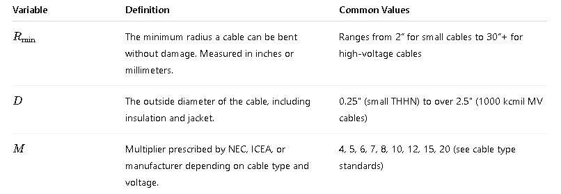
Where:

For Shielded Medium-Voltage Cables (ICEA S-93-639 / S-66-524):
- Shielded Cables (5kV to 35kV):
- Unshielded Medium-Voltage Cables:
- For Cable Terminations or Splices:
- Repeated Flexing or Dynamic Application:
Explanation of Each Variable in Detail

Cable Types and Their Typical Multipliers (Summary List)
| Cable Type | Standard | Multiplier MMM |
|---|---|---|
| THHN / XHHW | UL 83, NEC 310 | 8 |
| TC / MC Cable | UL 1277, NEC 336 | 7 |
| MV-105 Shielded | ICEA S-93-639 | 12 |
| Unshielded MV | ICEA S-93-639 | 8 |
| Fiber Optic (Static) | TIA/EIA-568 | 10 |
| Fiber Optic (Dynamic) | TIA/EIA-568 | 20 |
| Submarine or HVDC Cables | Manufacturer Spec | 15–20 |
Real-World Application Examples
Example 1: Data Center Using MV-105 Cables (15kV)
Scenario: A data center is installing shielded 15kV MV-105 copper cable, size 500 kcmil with OD = 1.45 inches. The routing includes a 90° turn in a cable tray.
Step-by-step Calculation:
- Identify cable type: MV-105 Shielded → Multiplier = 12
- OD = 1.45 in
- Use formula:
Result: The cable tray bend radius must be ≥ 17.4 inches.
Engineering Impact:
- Using a tighter radius (e.g., 12″) would violate NEC guidelines and risk insulation cracking or conductor breakage.
- Tray layout must include 36″ width to accommodate proper bending on both sides.
Example 2: Commercial Building Installing 250 kcmil XHHW-2 in Conduit
Scenario: A commercial contractor runs 250 kcmil XHHW-2, with an outside diameter of 0.85 inches, in a 3″ EMT conduit.
Step-by-step:
- Cable type: XHHW-2, 600V, non-shielded → Multiplier = 8
Result: Ensure any bends in conduit (e.g., elbows) maintain at least a 6.8-inch radius.
Notes:
- NEC 310.10 and manufacturer recommendations also suggest avoiding tight bends at terminations.
- Prefabricated 90° elbows must meet or exceed this radius.
Static vs. Dynamic Bending Radius: Why It Matters
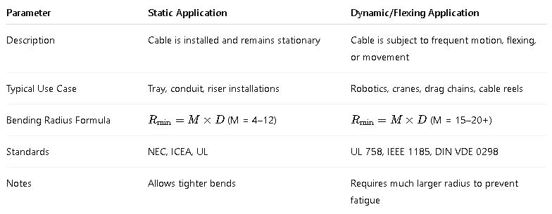
The bending radius requirement for a cable depends not only on the cable’s construction and voltage rating, but also on how the cable will be used. One of the most critical distinctions is between static and dynamic applications:

For repeated flexing, the minimum bending radius can be 20 times the cable diameter or more, depending on the frequency and speed of motion.
Special Cases: Fiber Optic, Coaxial, Armored, and Submarine Cables
Certain cable types are governed by different standards and have special bending radius requirements. Below is a breakdown of the most relevant ones.
1. Fiber Optic Cables
Fiber optic cables are extremely sensitive to bending because of light signal loss (attenuation) and micro-bending issues.
| Cable Type | Static Radius | Dynamic Radius | Standard |
|---|---|---|---|
| Indoor Tight Buffer | 10 × OD | 20 × OD | TIA/EIA-568, IEC 60794 |
| Outdoor Loose Tube | 15 × OD | 20–30 × OD | GR-20-CORE, Telcordia |
| Hybrid Fiber-Electrical (HFC) | 12 × OD | 24 × OD | ITU-T L.87 |
2. Coaxial Cables
For RF and video transmission, excessive bending leads to impedance mismatch and loss of signal integrity.
| Coax Type | Nominal OD | Min Bend Radius (Static) | Standard |
|---|---|---|---|
| RG-6 | 0.275″ | 2.75″ (10 × OD) | MIL-C-17 |
| RG-58 | 0.195″ | 2.0″ | MIL-C-17 |
| RG-11 | 0.405″ | 4.5″ | MIL-C-17 |
3. Armored and Metal-Clad (MC) Cables
These cables have steel or aluminum armor and are subject to mechanical restrictions during bending.
| Cable | Standard | Multiplier (M) |
|---|---|---|
| Armored MC Cable | NEC 330 | 7 × OD |
| Corrugated Sheath HV | Manufacturer Spec | 12–15 × OD |
| Interlocked Armor | UL 1569 | 7 × OD |
4. Submarine and HVDC Transmission Cables
These cables are highly specialized and require extensive bending radius planning during cable laying on seabeds or buried ducts.
| System | Typical Voltage | Bending Radius | Design Considerations |
|---|---|---|---|
| Submarine Power | 69kV–500kV | 15–25 × OD | Temperature, hydrostatic pressure, burial depth |
| Offshore Wind Farms | 33kV–132kV | 20 × OD | Combined with armor, gel-filled jackets |
| HVDC XLPE | 320kV–525kV | As per manufacturer | Usually ≥ 25 × OD |
Best Practices for Cable Installation with Respect to Bending Radius
To ensure compliance and preserve the long-term integrity of your cable system, follow these essential best practices:
Planning Phase
- Use CAD layouts to simulate bends and verify compliance with minimum bend radius.
- Account for space clearance in trays, conduits, junctions, and terminations.
During Installation
- Never pull or force cables around sharp corners.
- Use sheaves, rollers, and bend radii guides during heavy cable pulls.
- Maintain ambient temperature ≥ 5°C to avoid jacket brittleness.
- Avoid bundling cables tightly together in tight bends.
Post-Installation Checks
- Perform thermal imaging to detect hotspots caused by conductor stress.
- Use TDR (Time-Domain Reflectometry) for fiber/coaxial to check signal loss.


