Battery charging calculations ensure safe, efficient, and reliable energy storage performance across industrial, renewable, and transportation applications. IEC and IEEE standards define critical methods, formulas, and requirements for accurate battery charging, compliance, and long-term reliability.
Battery Charging Calculator — IEC & IEEE
Estimate charging current, C-rate, charging time and energy for batteries (Ah & V). Fast, accessible and WP-ready.
Typical C-rate guidance
- Li-ion: commonly 0.2C to 1C (fast charging often requires specialized cells)
- Lead-acid: typically 0.05C to 0.3C (avoid high C to prevent gassing)
- NiMH: commonly 0.1C to 0.5C
Always follow cell or battery pack manufacturer data sheets and relevant IEC/IEEE standards for charging profiles and safety.
Why efficiency matters
Why Accurate Battery Charging Calculations Matter
- Safety: Prevents overheating, gassing, and thermal runaway.
- Performance: Maximizes cycle life and ensures predictable runtime.
- Compliance: Aligns with IEC and IEEE design requirements.
- System Reliability: Guarantees uninterrupted performance for UPS, EV, telecom, and renewable storage.
Core Variables Used in IEC & IEEE Battery Charging Calculations
| Variable | Symbol | Units | Typical Range | Description |
|---|---|---|---|---|
| Nominal Voltage | Vn | V | 1.2 – 4.2 per cell | Defined by chemistry; used to calculate string voltage |
| Capacity | C | Ah | 1 – 5000 Ah | Ampere-hour rating, usually at 20 h discharge |
| Charge Current | Ic | A | 0.05C – 2C | Defined as a fraction of capacity |
| C-Rate | C-rate | h⁻¹ | 0.1C – 5C | Charging rate, relative to capacity |
| Charging Time | t | h | 0.5 – 20 h | Required to reach full SOC |
| Energy Input | Ein | Wh | V × Ah | Charging energy supplied |
| Efficiency | η | % | 80 – 98% | Ratio of stored energy to supplied energy |
| Temperature | T | °C | 0 – 45 °C | Recommended charging range |
Essential IEC & IEEE Charging Formulas
1. Charge Current from C-Rate
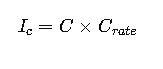
- Ic = Charge current [A]
- C = Battery capacity [Ah]
- C_rate = Selected charge rate (0.1C, 0.5C, 1C, etc.)
Typical values:
- Lead-acid (float): 0.05C – 0.2C
- Lithium-ion (fast charge): 0.5C – 2C
2. Charging Time Approximation
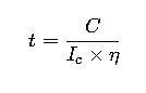
- t = Charging time [h]
- η = Charge efficiency (0.80–0.98 depending on chemistry)
3. Energy Input Requirement
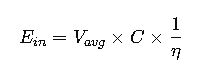
- Ein = Charging energy input [Wh]
- Vavg = Average charging voltage [V per cell]
4. Float Voltage (Lead-Acid, IEEE 1184 / IEC 60896)

- N = Number of series cells
5. Equalizing (Boost) Voltage for Lead-Acid
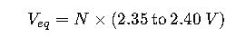
Used periodically to balance cell charge in stationary applications.
6. Lithium-Ion CC/CV Charging Method

Reference Tables for Common Values
Table 1. Typical Charge Current and Time per IEC & IEEE
| Chemistry | Capacity (Ah) | C-Rate | Current (A) | Efficiency (%) | Charge Time (h) |
|---|---|---|---|---|---|
| Lead-acid VRLA | 100 | 0.1C | 10 | 85 | ~12 |
| Lead-acid Flooded | 200 | 0.15C | 30 | 80 | ~14 |
| Li-ion (NMC) | 50 | 1C | 50 | 95 | ~1.1 |
| Li-ion (LFP) | 150 | 0.5C | 75 | 96 | ~3 |
| NiMH | 10 | 0.3C | 3 | 85 | ~4 |
| NiCd | 500 | 0.2C | 100 | 80 | ~6 |
Table 2. Float and Equalizing Voltages per Cell
| Chemistry | Float Voltage (V/cell) | Equalize / CV (V/cell) |
|---|---|---|
| Lead-acid VRLA | 2.23 – 2.27 | 2.35 – 2.40 |
| Flooded Lead-acid | 2.20 – 2.25 | 2.40 – 2.45 |
| Li-ion (NMC, LFP) | N/A | 4.20 (max) |
| NiMH | 1.40 trickle | 1.45 – 1.50 |
| NiCd | 1.40 trickle | 1.45 – 1.50 |
Table 3. Efficiency by Chemistry
| Chemistry | Charge Efficiency (%) | Notes |
|---|---|---|
| Lead-acid VRLA | 80 – 85 | Some gas evolution |
| Flooded Lead-acid | 75 – 85 | Temperature-dependent |
| Li-ion NMC | 95 – 98 | Excellent |
| Li-ion LFP | 92 – 96 | High efficiency |
| NiMH | 80 – 85 | Heat losses significant |
| NiCd | 75 – 85 | Robust but less efficient |
Real-World Engineering Examples
Case Study 1 – UPS with VRLA Batteries
Scenario:
A data center uses a 200 Ah, 240 V VRLA battery bank (108 cells). Engineers need float and equalize voltages and recharge time after 50% DoD.
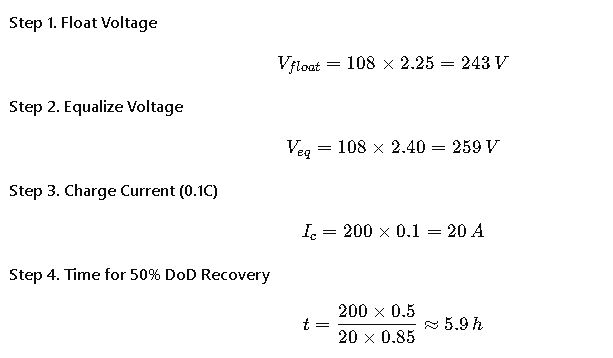
Result:
- Float voltage: 243 V
- Equalize voltage: 259 V
- Recharge after 50% DoD: ~6 h at 20 A
Case Study 2 – EV Lithium-Ion Pack
Scenario:
An EV pack has 96 cells (NMC, 50 Ah each). Nominal voltage: 355 V. The target is 1C fast charging.
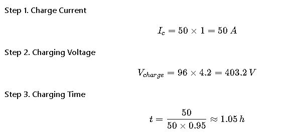
Result:
- Voltage: 403.2 V
- Current: 50 A
- Full charge: ~1.05 h
Additional Real-World Applications
Case Study 3 – Renewable Energy Storage with Lead-Acid Batteries
In remote solar power installations, stationary lead-acid banks remain one of the most common storage solutions. Consider a 1,000 Ah flooded lead-acid battery bank used for solar backup in an off-grid site.
- Float voltage settings: Engineers typically maintain 2.25 V/cell at 25 °C, aligned with IEC 60896.
- Equalization needs: Every 30–60 days, an equalizing charge at 2.40–2.45 V/cell is applied to prevent sulfation and maintain balance among cells.
- Charging current: For this type of system, 0.1C to 0.15C (100–150 A) is common, balancing efficiency and electrolyte health.
- Recharge time: After a deep cycle of 70% depth of discharge, recovery may take 12–14 hours, depending on available solar input.
This example demonstrates how charging calculations directly affect solar inverter design, PV array sizing, and daily energy availability. If the charging current is undersized, the batteries may never reach full state of charge, drastically reducing service life.
Case Study 4 – Telecom Tower with NiCd Batteries
Telecom operators often rely on nickel-cadmium (NiCd) batteries, especially in extreme climates where temperature variations are severe.
Imagine a 300 Ah NiCd string operating in a telecom tower in a desert region.
- Trickle charging: The system maintains 1.40 V/cell to keep the batteries topped up without generating excessive heat.
- Equalizing charge: During scheduled maintenance, the voltage is raised to about 1.50 V/cell to ensure cell uniformity.
- Efficiency considerations: NiCd systems are less efficient (75–85%), so chargers are oversized to compensate for energy losses.
- Temperature resilience: Unlike lithium-ion, NiCd can tolerate charging from –20 °C to +45 °C, making them ideal for remote telecom infrastructure.
This case highlights how the choice of chemistry and application environment influence all charging parameters, from voltage settings to charger capacity.
Temperature Correction Factors
Temperature has a major impact on battery charging. Both IEC and IEEE emphasize adjusting float and equalizing voltages according to ambient temperature.
Table 4. Temperature Coefficients for Charging Voltage
| Chemistry | Recommended Temperature Compensation | Notes |
|---|---|---|
| Lead-acid | –3 to –5 mV/°C per cell (from 25 °C reference) | Prevents overcharging at high temp |
| Li-ion | Usually no compensation (BMS controlled) | Protection handled by electronics |
| NiCd | –2 to –3 mV/°C per cell | Lower sensitivity compared to lead-acid |
Example:
For a VRLA battery operating at 35 °C (10 °C above nominal), the float voltage per cell should be reduced by approximately 40 mV to avoid excessive gassing and water loss.
Charger Sizing Considerations
When designing or specifying a charger, engineers follow both IEC and IEEE recommendations:
- Charge Current Rating
- For lead-acid: 10–20% of rated capacity is standard.
- For lithium-ion: 0.5C to 1C is typical in EV and fast-charge systems.
- Redundancy
- In telecom and data centers, N+1 redundancy ensures uninterrupted operation.
- Efficiency Margins
- Chargers are usually oversized by 10–25% to account for efficiency losses, aging, and temperature effects.
- Integration with Control Systems
- Modern chargers integrate with battery management systems (BMS) or supervisory control and data acquisition (SCADA) systems to provide alarms, telemetry, and adaptive charging algorithms.
Extended Reference Tables
Table 5. Depth of Discharge vs. Recharge Time (Lead-Acid, IEC 60896)
| DoD (%) | Typical Recharge Time (at 0.1C) |
|---|---|
| 20% | 3–4 h |
| 40% | 5–6 h |
| 50% | 6–8 h |
| 70% | 10–12 h |
| 100% | 14–16 h |
Table 6. Typical Applications and Charging Practices
| Application | Common Chemistry | IEC/IEEE Standard | Charging Strategy |
|---|---|---|---|
| Data Centers | VRLA | IEEE 1184 | Float + periodic equalization |
| EV Charging | Li-ion NMC | IEC 61960 | CC/CV fast charging |
| Renewable Storage | Flooded Lead-acid | IEC 60896 | Bulk + absorb + float |
| Telecom Towers | NiCd | IEEE 1115 | Trickle + scheduled equalization |
| Consumer Electronics | Li-ion | IEC 61960 | CC/CV with BMS control |
Compliance and International Standards
Adherence to standards is not optional; it is essential for safety and interoperability.
- IEC 61960: Defines testing, charging, and safety requirements for lithium-ion batteries.
- IEC 60896: Covers stationary lead-acid batteries, widely used in UPS and renewable storage.
- IEEE 485: Guides battery sizing and charging requirements for stationary applications.
- IEEE 1184: Provides detailed practices for VRLA battery management.
- IEEE 1115: Specialized standard for NiCd batteries in telecom systems.
These documents provide reference voltages, charging methods, test procedures, and correction factors. For professional projects, engineers should always cross-check calcula
tions with the most recent edition of these standards.Industry Best Practices
- Avoid Overcharging: Excessive voltage accelerates aging, electrolyte loss, or thermal runaway.
- Use Temperature Sensors: Always compensate voltage for ambient variations.
- Integrate Smart Charging: BMS or charger controllers dynamically adjust current and voltage.
- Size Chargers Properly: Undersized chargers prolong recovery time; oversized chargers increase cost and risk.
- Periodic Maintenance: Especially for lead-acid, equalizing charges and periodic inspections are essential.
Key Takeaways
- Charging calculations determine current, voltage, efficiency, and energy input.
- IEC and IEEE standards provide harmonized frameworks for different chemistries.
- Real-world applications vary: UPS, EV, renewable storage, and telecom each require specific approaches.
- Environmental factors (temperature, DoD, efficiency) strongly affect results.
- Compliance ensures safe, reliable, and long-lasting operation of battery systems.