This expert guide to UPS battery sizing provides complete formulas, variable definitions, and reference tables. It includes Peukert corrections, charger sizing, and real-world worked examples, citing IEC, IEEE, and manufacturers.
UPS Battery Calculator — Battery Capacity & Runtime Estimator
Quickly size battery banks for UPS systems: required Ah, recommended series/parallel layout, and runtime estimates.
How does this calculator work?
Key formulas
Battery Ah = Battery_energy_Wh / Battery_bank_voltage.
Adjust for DoD: usable_capacity = rated_capacity × (DoD%).
Why specify DoD?
Quick reference tables — common UPS battery configurations and typical values
Table 1 — Common nominal DC bus voltages and the number of 12 V / 2 V blocks required
| Nominal DC bus (typical UPS designs) | Typical 12 V blocks in series | Equivalent 2 V cells in series (approx.) | Notes |
|---|---|---|---|
| 24 V | 2 × 12 V | 12 × 2 V | Small UPS / telecom edge. |
| 48 V | 4 × 12 V | 24 × 2 V | Very common for small to medium UPS and telecom. |
| 96 V | 8 × 12 V | 48 × 2 V | Mid-range systems / battery cabinets. |
| 120 V | 10 × 12 V | 60 × 2 V | Some legacy UPS/DC systems. |
| 144 V | 12 × 12 V | 72 × 2 V | Often used in larger single-phase UPS. |
| 180 V | 15 × 12 V | 90 × 2 V | Large UPS strings. |
| 192 V | 16 × 12 V | 96 × 2 V | Very common for 10–50 kVA server room UPS. |
| 240–384 V | 20–32 × 12 V | 120–192 × 2 V | Medium/large data centre UPSs (modular). |
| > 400 V | Depends on design | Often built from 2 V cells | High-voltage systems and industrial UPSs. See IEC limits. |
Practical note: manufacturers often specify the exact nominal DC input voltage (e.g., 192 V nominal) — always match string voltage to the UPS DC bus per the manufacturer.
Table 2 — Typical battery block Amp-hour (Ah) sizes used in UPS systems and use cases
| Common block size (12 V) | Typical application | Typical continuous discharge C-rate used in UPS | Notes |
|---|---|---|---|
| 7–12 Ah | Small tower UPS (desktop/server closet) | C/5 to 1C | Small sealed lead-acid for network/PC backup. |
| 17–65 Ah | Small rack UPS, telecom | C/5 to C/2 | Common VRLA/AGM hot-swap battery packs. |
| 100–150 Ah | Small data center / in-room battery cabinets | C/10 to C/1 | Stationary VRLA / tubular flooded options. |
| 200–300 Ah | Telecom exchanges / large UPS strings | C/20 to C/2 | Industrial stationary batteries. |
| 400 + Ah | Large standby / energy storage | low C (C/20) | Often flooded or advanced VRLA in large banks. |
Table 3 — Instant reference: Wh stored and approximate runtime (no Peukert) for common combos
(Assumptions: nominal V, Ah block as shown, single series string, inverter & battery round-trip efficiency combined = 0.90; usable DOD fraction = 0.50 unless noted.)
| System (V) | Block Ah | Energy stored Wh (V×Ah) | Usable energy @50% DOD (Wh) | Approx. runtime for 2 kW load (h) |
|---|---|---|---|---|
| 48 V × 100 Ah | 100 | 4,800 Wh | 2,400 Wh | 1.20 h |
| 192 V × 100 Ah | 100 | 19,200 Wh | 9,600 Wh | 4.8 h |
| 192 V × 150 Ah | 150 | 28,800 Wh | 14,400 Wh | 7.2 h |
| 48 V × 200 Ah | 200 | 9,600 Wh | 4,800 Wh | 2.4 h |
These are simplified reference numbers for initial planning only. Real runtime must include inverter efficiency, Peukert effect at high currents, temperature derating and recommended reserve. See examples below for full worked calculations.
Fundamental formulas for UPS battery calculation (complete set) — derivations & variable explanations
I list below the formulas you will use repeatedly, with exact variable definitions, typical values, and practical guidance on which factors to include for accurate, standards-aware sizing.
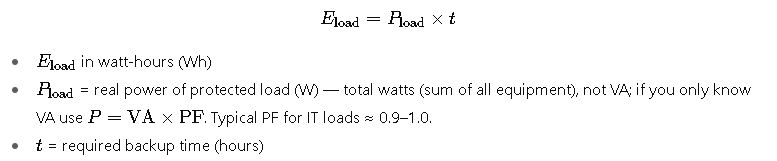
1) Energy required by the load (AC)
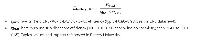
2) DC energy drawn from the battery (accounts for inverter efficiency and battery discharge efficiency)
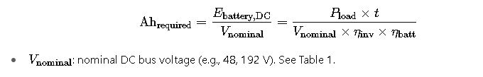
3) Required nominal battery capacity in ampere-hours (Ah)
4) Adjust for desired Depth-of-Discharge (DOD) (to obtain rated capacity)

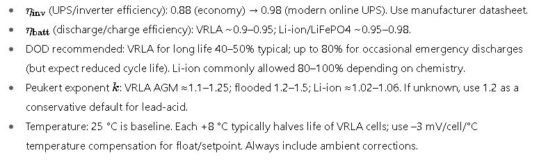
- DOD: fraction of the battery you allow to use (0.5 for 50% DOD, 0.8 for 80%). For long life, VRLA lead-acid often sized for 40–50% usable DOD; telecom/short emergency runs sometimes allow 80% for heavy events. See manufacturer guidance and standards.
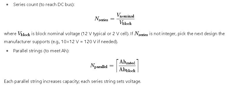
5) Number of batteries in series and parallel
6) Peukert correction (accounts for rate-dependent capacity reduction)
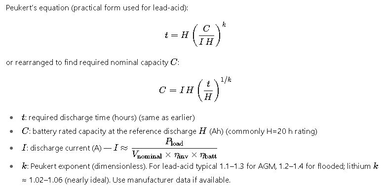
Why Peukert matters: at high discharge currents the effective Ah capacity can be significantly lower than the rated 20-h capacity — so for short but very large load events you must size for Peukert, not the simple Ah formula.
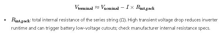
7) Battery internal resistance and terminal voltage under load
Approximate instantaneous terminal voltage under load:
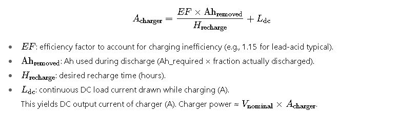
8) Battery charger sizing (to meet a given recharge time and continuous load while recharging)
Common practical formula:
Typical variable values and ranges — what to assume in practice
Real-world application — fully worked examples (step-by-step)
All numeric arithmetic below is computed exactly and shown; I include Peukert & charger sizing where relevant so results are engineering-grade.
Case A — Small site: A 5 kW server rack needs 30 minutes (0.5 h) of UPS back-up (48 VDC battery string)
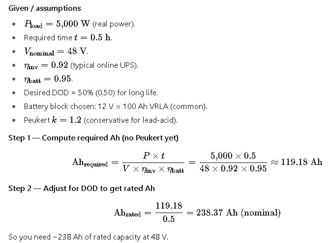
Step 3 — Map to blocks (series & parallel)
- Series = 48 V / 12 V = 4 blocks in series. Each string capacity = block Ah (100 Ah).
- Parallel strings required = ceil(238.37 / 100) = 3 strings in parallel → total battery bank = 4 (series) × 3 (parallel) = 12 × 12 V, 100 Ah blocks (effective nominal capacity 300 Ah). This yields margin and better handle Peukert and temperature.
Step 4 — Peukert check (does 3×100Ah satisfy rate?)
Battery current during discharge:
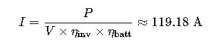
Per parallel string current = 119.18 / 3 ≈ 39.7 A ≈ 0.397C (for 100 Ah block) — moderate C-rate. Using Peukert withk=1.2 and H=20 h, required capacity computed by Peukert formula gives ~110 Ah (see earlier analysis), and 3×100 Ah (300 Ah total) is more than adequate. The chosen 3-string configuration is robust and provides safety margin for aging and temperature.
Step 5 — Charger sizing (target: recharge to 85% in 8 h after full discharge)
Assume you used 50% of rated bank (which is the design), Ah removed ≈ 119.18 (from step 1). Use EF=1.15, desired H=8 h, L=DC load while charging ≈ 0 (or include the running server draw if the UPS charges while powering the load):
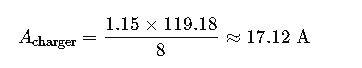
Charger power ≈ 48 V × 17.12 A ≈ 822 W. Round up to next standard charger size and include temperature compensation.
Commentary & best practice (Case A): choose VRLA blocks with capacity ≥120 Ah if you want fewer parallel strings; ensure battery cabinet ventilation and 25 °C baseline; include periodic load tests per IEEE/IEC guidance.
Case B — Data-centre sized run: 50 kW critical load, 15 minutes runtime, 192 V DC battery string (typical mid-sized UPS)
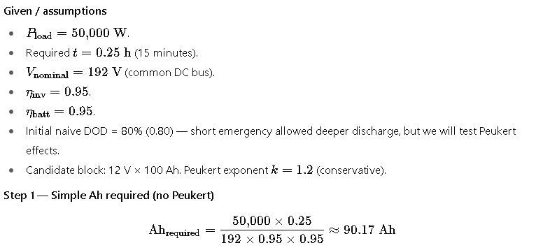
Naively dividing by DOD 0.8 gives rated Ah ≈ 112.7 Ah — that suggests one 100 Ah string would be borderline. But this ignores Peukert.
Step 2 — Compute battery pack current and Peukert correction
Battery pack current during discharge:
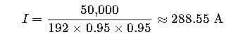
If using a single 100 Ah string, C-rate ≈ 2.885C — high; Peukert capacity collapse is significant. Using Peukert formula (H=20 h, k=1.2) solve for required rated capacity C to supply t=0.25 h at current I:

So to actually supply 15 minutes at this high current with lead-acid chemistry you need roughly 150 Ah (20-h rating), not 100 Ah. That means either select 12 V × 150 Ah modules in a single series string (16×150 Ah → 192 V) or use two parallel 100 Ah strings (giving 200 Ah total rated) which also meets the requirement and gives margin for aging. Using 1×100 Ah would not reliably deliver 15 minutes at 50 kW when Peukert is considered.
Step 3 — Choose final configuration & charger sizing
Option chosen: 16 × 150 Ah (1 string) or 16 × (2 parallel × 100 Ah) = 32 × 12 V (2 strings) — both acceptable. If we select 150 Ah single string, Ah_rated = 150 Ah, DOD limit for short event 80% → usable Ah = 120 Ah which matches required Ah ≈ 90.17 with Peukert margin.
Charger sizing example if full 80% used (Ah_removed ≈ 120 Ah) and we want recharge to 85% in 8 h with EF=1.15:
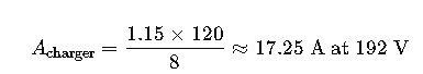
Charger power ≈ 192 V × 17.25 A ≈ 3.31 kW. Round up and include temperature compensation.
Commentary & standards: for large UPS systems consult IEC 62040 family and IEEE practices (e.g., IEEE 485/450 guidance for stationary battery sizing and maintenance). Always validate Peukert exponent with battery datasheet because the exponent influences required capacity strongly for short, high currents.
Temperature, aging, and maintenance adjustments (how to derate)
- Temperature derating: battery capacity and life are temperature sensitive. VRLA optimum is ~25 °C; each +8 °C halves life (rule-of-thumb). For capacity, cold reduces available Ah (e.g., at −18 °C capacity may fall to ~50%). Always size with ambient correction factors; include thermal management for battery rooms.
- Aging: battery capacity declines with age (typical VRLA life 3–6 years depending on temperature and cycling). Include cycling reserve or oversize the bank to allow capacity fade (e.g., design for 80–85% of new capacity at end-of-life). Follow IEEE/IEC recommended test regimes.
- Maintenance & testing: periodic discharge tests, impedance / conductance tests and thermal checks per IEEE recommendations prolong life and verify assumptions. Keep accurate logs.
Practical checklist — things you must check when doing a UPS battery calculation
- Confirm real power (W) of the load — do not size using VA alone without PF.
- Confirm UPS inverter efficiency (manufacturer datasheet) for the actual load range.
- Select nominal battery voltage to match the UPS DC bus (do not approximate).
- Choose battery chemistry (VRLA vs Li-ion) — affects DOD, Peukert, temperature behaviour and charger strategy.
- Always include Peukert correction for short, high-current events (k matters).
- Apply temperature and aging derating and select charger with temperature compensation.
- Size charger for targeted recharge time and any continuous DC loads (formula provided earlier).
- Plan for N+1 or redundancy and safe working clearances, and follow IEC 62040 / IEEE guidance for installation & testing.