Automatic Transfer Switches (ATS) are essential devices that enable reliable, seamless power transfer during failures. They protect loads by switching between utility and backup sources, ensuring continuity in sensitive, mission-critical facilities.
ATS & Settings Calculator — IEEE / IEC
Why these values?
Formulas & logic
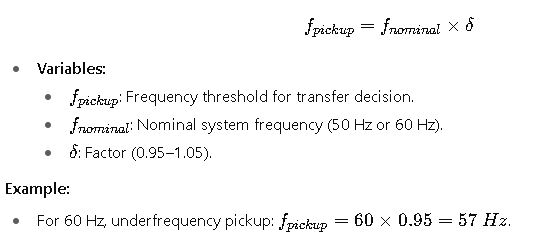
• Frequency thresholds are absolute (Hz).
• Sensing time (ms) prevents nuisance transfers from transients; transfer delay (s) is how long ATS waits before executing.
• Generator loading check: ATS compares rated load current vs generator continuous current (kVA·power factor) and shows margin.
Comprehensive Tables of ATS Settings – IEEE & IEC Reference Values
The following tables summarize common ATS pickup, dropout, and delay settings based on IEEE and IEC recommendations. These values are representative of widely adopted industry practices but should always be fine-tuned based on load criticality, generator characteristics, and local codes.
Table 1: Voltage Sensing Settings for ATS (Typical IEEE/IEC Ranges)
| Parameter | IEEE Recommended Value | IEC Recommended Value | Common Range in Practice |
|---|---|---|---|
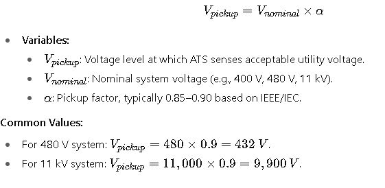
| Undervoltage Pickup (% of nominal) | 85–90% | 85–90% | 0.85–0.90 × Vn |
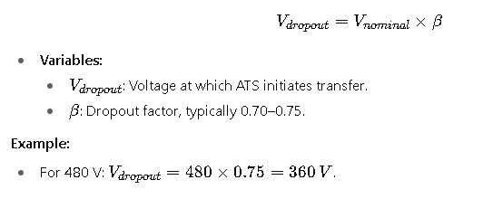
| Undervoltage Dropout (% of nominal) | 70–75% | 70–75% | 0.70–0.75 × Vn |
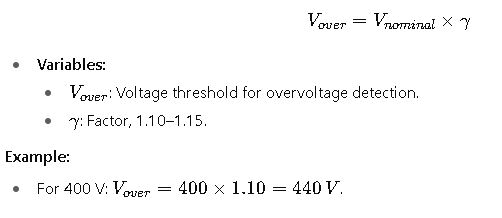
| Overvoltage Pickup (% of nominal) | 110–115% | 110–115% | 1.10–1.15 × Vn |
| Overvoltage Dropout (% of nominal) | 105–110% | 105–110% | 1.05–1.10 × Vn |
| Unbalanced Voltage (Phase imbalance) | 10% | 8–10% | 0.08–0.10 × Vn |
Table 2: Frequency Sensing Settings for ATS (Typical IEEE/IEC Ranges)
| Parameter | IEEE Recommended Value | IEC Recommended Value | Common Range in Practice |
|---|---|---|---|
| Underfrequency Pickup (Hz) | 95–97% of nominal | 95–97% of nominal | 0.95–0.97 × fn |
| Underfrequency Dropout (Hz) | 90–93% of nominal | 90–93% of nominal | 0.90–0.93 × fn |
| Overfrequency Pickup (Hz) | 103–105% of nominal | 103–105% of nominal | 1.03–1.05 × fn |
| Overfrequency Dropout (Hz) | 107–110% of nominal | 107–110% of nominal | 1.07–1.10 × fn |
| Frequency Deviation (Hz/s – ROCOF) | 0.5–1.0 Hz/s | 0.5–1.0 Hz/s | 0.5–1 Hz/s |
Table 3: Transfer and Retransfer Delay Settings
| Parameter | IEEE Recommendation | IEC Recommendation | Common Range in Practice |
|---|---|---|---|
| Transfer Delay (utility → generator) | 0–3 sec | 0–3 sec | 0–5 sec |
| Retransfer Delay (generator → utility) | 30–180 sec | 30–180 sec | 30–300 sec |
| Generator Warm-Up Delay | 5–15 sec | 5–15 sec | 5–30 sec |
| Generator Cool-Down Delay | 5–10 min | 5–10 min | 5–10 min |
| In-Phase Transfer Window (sync) | ±5° | ±10° | ±5–10° |
Table 4: Common Load-Specific ATS Settings
| Application Type | Undervoltage Pickup | Retransfer Delay | Generator Warm-Up | Cool-Down Delay |
|---|---|---|---|---|
| Hospitals (life safety) | 90% Vn | 30–60 sec | 5–10 sec | 10 min |
| Data Centers | 85–90% Vn | 120 sec | 10–15 sec | 5–8 min |
| Industrial Plants | 85% Vn | 180–300 sec | 10 sec | 5 min |
| Commercial Buildings | 85–90% Vn | 60–120 sec | 10 sec | 5 min |
| Airports / Critical Transport | 90% Vn | 30–60 sec | 5 sec | 10 min |
Core Formulas for ATS Settings Calculation (IEEE & IEC)
To properly configure an ATS, engineers must apply standardized formulas to compute pickup, dropout, and timing thresholds. Below are the most relevant formulas along with detailed explanations of each variable.
1. Undervoltage Pickup Formula
2. Undervoltage Dropout Formula
3. Overvoltage Pickup Formula
4. Frequency Pickup (Under/Over)
Real-World Application Cases of ATS Settings – IEEE & IEC
The practical application of Automatic Transfer Switch (ATS) configurations highlights the importance of correct parameter selection. Misconfigured settings can lead to unnecessary transfers, equipment stress, or even system failure. Below are two detailed real-world case studies demonstrating how ATS settings are applied under IEEE and IEC frameworks.
Case Study 1: ATS in a Hospital Emergency Power System
Context:
A 480 V, 60 Hz hospital facility requires an ATS to transfer life-safety loads (operating rooms, intensive care units, emergency lighting) to an emergency generator upon utility power failure. The hospital follows NFPA 110, IEEE 446, and IEC 60947-6-1 recommendations.
Engineering Considerations:
- Transfer Speed: For life safety, the ATS must transfer within 10 seconds, as mandated by NFPA 110.
- Voltage Sensitivity: Critical medical equipment requires tight voltage regulation; undervoltage pickup must not fall below 90% of nominal.
- Frequency Stability: Generator frequency variation is allowed during load acceptance, but the ATS must avoid premature retransfer.
- Warm-Up and Cool-Down: Generator warm-up is set at 5 seconds to ensure stable output before load acceptance. Cool-down delay is 10 minutes to allow proper cooling of the generator.
Settings Applied:
- Undervoltage Pickup: 90% of 480 V = 432 V.
- Undervoltage Dropout: 75% of 480 V = 360 V.
- Transfer Delay (utility → generator): 1 second.
- Retransfer Delay (generator → utility): 30 seconds (fast return for reliability).
- Generator Warm-Up: 5 seconds.
- Cool-Down Delay: 10 minutes.
Operational Result:
During a utility outage, the ATS detected voltage below 360 V, initiated transfer, waited for 5 seconds of generator stability, and restored critical loads in under 10 seconds. Once the utility returned, the ATS monitored for 30 seconds of stable voltage before retransfer. This configuration ensured compliance with IEEE/IEC and eliminated any risk of medical equipment disruption.
Case Study 2: ATS in a Data Center with Redundant Utility Feeds
Context:
A Tier III data center operating at 11 kV medium voltage uses two independent utility feeders (primary and secondary) with an ATS configured for high reliability. IEEE Std 1547, IEC 60947-6-1, and Uptime Institute requirements apply.
Engineering Considerations:
- Load Criticality: Continuous IT load must not experience interruptions longer than 100 ms, requiring closed-transition ATS with in-phase transfer capability.
- Voltage Settings: Data center UPS systems can tolerate undervoltage down to 85%, but ATS should act conservatively to prevent stress on UPS inverters.
- Frequency Settings: Since utility feeds are stable, frequency thresholds are narrow: underfrequency at 97%, overfrequency at 103%.
- Synchronization: In-phase transfer must occur within ±5 electrical degrees to avoid transient torque on UPS rectifiers and generators.
- Retransfer Delay: Extended to 180 seconds to confirm stability of the recovered primary feeder before switching back.
Settings Applied:
- Undervoltage Pickup: 90% of 11 kV = 9.9 kV.
- Undervoltage Dropout: 85% of 11 kV = 9.35 kV.
- Transfer Delay (primary → secondary): 0.5 seconds (fast for IT load).
- Retransfer Delay: 180 seconds.
- In-Phase Transfer Window: ±5°.
- Generator Warm-Up/Cool-Down: Not applicable (dual-utility redundancy).
Operational Result:
When the primary feeder dipped to 9.2 kV during a grid disturbance, the ATS sensed undervoltage, validated the event for 0.5 seconds, and executed a closed-transition transfer to the secondary feeder. The in-phase synchronization feature ensured zero-load drop for IT servers, preserving 100% uptime compliance with Tier III certification.
Key Challenges in ATS Settings
Even when following IEEE and IEC standards, engineers must address several practical challenges in ATS configuration:
- Generator Behavior: Small generators may exhibit large voltage/frequency swings upon load acceptance. Settings must balance sensitivity and tolerance.
- Nuisance Transfers: If undervoltage pickup is set too high, normal voltage fluctuations can trigger false transfers.
- Coordination with UPS and PLCs: For data centers and industrial plants, ATS timing must coordinate with UPS ride-through and process automation restart logic.
- Environmental Factors: High altitude and temperature can affect generator performance, requiring adjusted ATS settings.
- Regulatory Compliance: NFPA 110 (hospitals), IEEE 446 (industrial power), IEC 60947-6-1 (switchgear) all specify unique requirements that must be harmonized.
Authoritative References for ATS Standards
For engineers and designers seeking to go deeper, the following references provide comprehensive detail:
- IEEE 446 – IEEE Recommended Practice for Emergency and Standby Power Systems for Industrial and Commercial Applications
- IEEE 1547 – Standard for Interconnection and Interoperability of Distributed Energy Resources
- IEC 60947-6-1 – Low-Voltage Switchgear and Controlgear – Multiple Function Equipment
- NFPA 110 – Standard for Emergency and Standby Power Systems
- National Electrical Manufacturers Association (NEMA) ATS guidelines
- IEC Official Standards