Explore concise arc-flash tables highlighting critical IEEE 1584 parameters, boosting electrical safety knowledge and compliance.
Leverage NFPA 70E-aligned results to select PPE confidently, reduce downtime, and protect skilled maintenance teams.
Arc-Flash Incident-Energy Calculator
Uses the IEEE 1584-2002 empirical equation (208 V – 15 kV).
Good for fast PPE screening—run a full study for final labels.
Formula: En = Cf · Ibf · t · (610⁄D)1.4738 cal/cm²
Coefficients from IEEE 1584-2002 empirical model (Cf adjusted for configuration ± box factor).
Standard used: IEEE Std 1584-2002 (screening method). This calculator does not implement the
2018 algorithm, which requires additional inputs and iterative steps.
Disclaimer: Results are preliminary and conservative. They do not replace a full
arc-flash hazard analysis by a qualified engineer.
Not for Professional Use: Please ensure that any user of this calculator clearly understands it’s not for professional risk analysis or for compliance with safety standards. For those purposes, specialized software tools and qualified personnel must be used.
Artificial Intelligence (AI) Calculator for “Arc Flash Incident Energy Calculator – NFPA 70E, IEEE 1584”
Arc Flash Data Tables (Typical Values)
Below are comprehensive tables summarizing typical input parameters and results used in arc flash incident energy calculations as defined by IEEE 1584 and NFPA 70E.
Table 1: Common System Parameters
| Parameter | Typical Range | Unit | Description |
|---|---|---|---|
| System Voltage | 208 – 13,800 | Volts (V) | Line-to-line voltage of electrical system |
| Bolted Fault Current | 2 – 65 | kA | Available symmetrical short-circuit current |
| Arc Duration | 0.05 – 2 | Seconds (s) | Duration the arc exists before interruption |
| Working Distance | 305 – 914 | mm | Distance between worker and arc source |
| Electrode Gap (G) | 13 – 76 | mm | Distance between conductive parts that sustain arc |
| Equipment Type | VCB, VCBB, HCB, HOA | N/A | Configuration of equipment and electrode arrangement |
| Enclosure Type | Metal-enclosed / Open | N/A | Affects arc behavior and incident energy |
Formulas for Arc Flash Incident Energy Calculation (Corrected per IEEE 1584-2018)
The empirically derived arc current formula from IEEE 1584-2018 is:
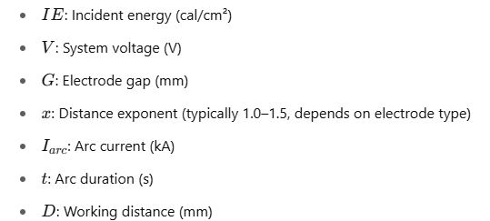
Where:

Where:

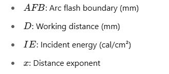
3. Arc Flash Boundary (AFB)
Where:

4. Energy Conversion (Cal to Joules)
Real-World Examples
Example 1: MCC Operating at 480V
System Parameters:
- Voltage = 480 V
- Bolted Fault Current = 25 kA
- Arc Duration = 0.3 seconds
- Working Distance = 457 mm
- Gap Between Conductors = 32 mm
- Electrode Configuration = VCBB
Steps:

Result:
- Arc Current: ~19.8 kA
- Incident Energy: 6.5 cal/cm²
- Arc Flash Boundary: 1035 mm
Example 2: 13.8kV Switchgear
System Parameters:
- Voltage = 13,800 V
- Bolted Fault Current = 10 kA
- Arc Duration = 0.5 seconds
- Working Distance = 914 mm
- Gap Between Conductors = 76 mm
- Electrode Configuration = HCB
Result:
- Arc Current: ~7.4 kA
- Incident Energy: 4.2 cal/cm²
- Arc Flash Boundary: 786 mm
Additional Notes
- IEEE 1584-2018 introduces five electrode configurations: VCB, VCBB, HCB, HOA, and HAA.
- Always use software tools like SKM, ETAP, or EasyPower to handle complex coefficients and modeling.
- NFPA 70E defines the threshold of 1.2 cal/cm² as the limit for second-degree burn risk.
- Calculation accuracy depends on proper identification of electrode configuration, gap distance, and arc duration, which should be aligned with protective device clearing time.
- Always verify that the short-circuit current falls within IEEE 1584’s recommended range: 500 A to 106,000 A.


