This article explains precise methods to size buck‑boost transformers for voltage correction tasks and safety.
It covers instant kVA calculation from voltage correction, load current, phase configuration, and standards guidance.
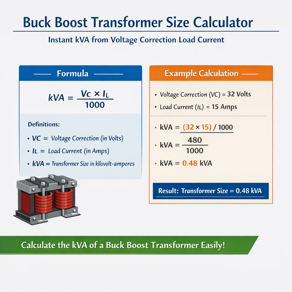
Buck-Boost Transformer Size Calculator – Instant kVA from Voltage Correction and Load Current
Fundamental theory and practical significance
A buck‑boost transformer is a small autotransformer or isolation transformer used to adjust supply voltage by a small amount, typically ±5–10%. In practice these units are connected in series with the supply to "buck" (reduce) or "boost" (raise) the delivered voltage to the load without replacing the main transformer. Correct sizing of a buck‑boost unit must be based on the instantaneous volt‑ampere demand created by the required voltage correction and the load current, not on the total load kW or kVA alone.The core technical point is that the transformer must supply the corrective voltage at the full load current. Therefore the required VA (or kVA) of the buck‑boost transformer equals the product of the corrective voltage (volts) and the current through that winding (amperes), summed appropriately for the number of phases and connection type. Proper sizing ensures thermal limits, inrush characteristics, and regulatory requirements are satisfied.Key formulas for instant kVA from voltage correction and load current
Single‑phase (series correction)
- V_correction = V_nominal × (percent_correction / 100)
- I_load = load current (amperes) flowing through the buck‑boost winding
- Typical values: V_nominal = 120 V or 240 V; percent_correction = ±1% to ±10%
Three‑phase (methods depend on connection)
When applying three single‑phase buck‑boost units in series with each phase (common installation):
If the correction value is specified as a line‑to‑line (V_LL) correction on a wye system, convert to phase voltage first:
- Notation: √3 ≈ 1.732
- I_phase = phase current (for balanced loads I_phase = I_line on wye)
- Typical voltages: 208 V, 400 V, 480 V (line‑to‑line)
Voltage correction from percentage
Examples of percent_correction: +5% means boosting voltage by 5% of nominal.
Variable definitions, typical ranges, and selection notes
- V_nominal — system nominal voltage (V): typical 120, 208, 240, 415, 480 V.
- percent_correction — percent of V_nominal to be added or subtracted: typical ±1% to ±10% (manufacturers often limit to ±10%).
- V_correction — resulting corrective voltage (V) = V_nominal × percent_correction / 100.
- I_load / I_phase — continuous load current (A). Use continuous current per NEC/standards including demand factors where applicable.
- kVA — required apparent power rating of buck‑boost transformer in kilovolt‑ampere.
- Service type — continuous vs intermittent; for continuous duty choose transformer rated for continuous operation at computed kVA or higher.
- Configuration — single‑phase buck‑boost or three single‑phase units vs single three‑phase transformer; three single‑phase units are common for series correction on three‑phase systems.
Step‑by‑step sizing procedure
- Determine nominal system voltage (V_nominal) and whether the correction is line‑to‑line or phase‑to‑neutral.
- Determine required percent_correction (based on measurement or design target) and compute V_correction = V_nominal × percent_correction / 100.
- Measure or calculate load current (I_load or I_phase) at the location where correction will be applied.
- Choose appropriate formula from section above depending on single‑phase, three‑phase wye, or delta.
- Compute kVA_required from kVA formula and then select next‑standard manufacturer's size with margin (typical margins: 10–25% depending on inrush and ambient).
- Check regulatory and thermal constraints (NEC continuous load rules, ambient derating, harmonics) and increase size if necessary.
Extensive tables for common voltages, correction percentages, and currents
| Case | System | V_nominal (V) | Percent correction (%) | V_correction (V) | I_load (A) | kVA required (single‑phase) kVA |
|---|---|---|---|---|---|---|
| 1 | Single‑phase | 120 | +5 | 6.0 | 10 | 0.06 |
| 2 | Single‑phase | 120 | +5 | 6.0 | 50 | 0.30 |
| 3 | Single‑phase | 240 | -5 | 12.0 | 75 | 0.90 |
| 4 | Single‑phase | 240 | +10 | 24.0 | 100 | 2.40 |
| 5 | Single‑phase | 230 | +3 | 6.9 | 30 | 0.207 |
| Case | System | V_nominal (LL) (V) | Percent corr. (%) | V_LL_correction (V) | I_line (A) | kVA required (3‑phase, wye) kVA |
|---|---|---|---|---|---|---|
| A | 3‑phase wye | 208 | +5 | 10.4 | 50 | √3×10.4×50/1000 = 0.902 |
| B | 3‑phase wye | 480 | +4 | 19.2 | 100 | √3×19.2×100/1000 = 3.326 |
| C | 3‑phase wye | 415 | -3 | 12.45 | 200 | √3×12.45×200/1000 = 4.316 |
| D | 3‑phase delta | 480 | +5 | 24.0 | 150 | 3×24×150/1000 = 10.8 |
| E | 3‑phase wye | 690 | +2 | 13.8 | 250 | √3×13.8×250/1000 = 5.979 |
Notes: For table B, use √3 ≈ 1.732 in numerical evaluation. Values in table are rounded to three decimals where applicable.
Detailed worked examples
Example 1 — Single‑phase facility lighting correction
Scenario: A commercial site has a single‑phase 240 V lighting circuit with continuous current 75 A. Measured voltage is 252 V but fixtures are rated for 240 V nominal with optimal operation at 240 V. The designer wants to buck the supply by 5% to bring the voltage to nominal. Select an appropriate buck‑boost transformer.
- Compute percent correction: percent_correction = −5% (we want to reduce by 5%).
- Compute V_correction: V_correction = 240 × 0.05 = 12 V.
- Compute required kVA (single‑phase): kVA = (V_correction × I_load) / 1000 = (12 × 75) / 1000 = 900 / 1000 = 0.9 kVA.
- Select transformer size: Choose a commercially available buck‑boost transformer rated at least 0.9 kVA. Apply margin—choose next standard size, e.g., 1 kVA or 1.5 kVA to allow for heating, inrush, and ambient; many manufacturers list 1 kVA 240 V buck‑boost models.
- Verify continuous duty: Lighting is continuous per NEC; ensure selected unit is rated for continuous operation at 100% nameplate or apply 125% sizing if required by local code.
- Check connections: Use proper series connection wiring and ensure primary/secondary tap orientation produces buck (subtractive) voltage.
Result: Minimum kVA = 0.9 kVA. Recommended commercial selection: 1.5 kVA buck‑boost transformer with continuous rating and correct tap configuration to buck 12 V at 75 A.
Example 2 — Three‑phase motor bank boost on a 480 V wye system
Scenario: A three‑phase motor bank connected to a 480 V wye supply draws 100 A line current per phase at full load. Measured voltage has sag and the engineer elects to boost the system by 4% to recover voltage and torque. Determine buck‑boost sizing and selection.
- Nominal line‑to‑line voltage V_LL_nom = 480 V.
- Percent correction = +4% → V_LL_correction = 480 × 0.04 = 19.2 V.
- For wye system, kVA_total = √3 × V_LL_correction × I_line / 1000.
- Compute: √3 ≈ 1.732; so kVA_total = 1.732 × 19.2 × 100 / 1000 = 1.732 × 1920 / 1000 = 3327.84 / 1000 = 3.32784 kVA ≈ 3.33 kVA.
- Selection: Choose three single‑phase buck‑boost units rated to supply V_phase_correction = V_LL_correction / √3 = 19.2 / 1.732 ≈ 11.09 V at I_phase = 100 A per unit. Per phase VA = 11.09 × 100 = 1109 VA ≈ 1.109 kVA; total ≈ 3.33 kVA as found.
- Choose standard unit: Select per‑phase unit ≥1.25 kVA or choose one three‑phase autotransformer rated ≥4 kVA to provide margin (10–25%) and to allow continuous operation and inrush handling.
- Verify motor starting: If motors produce high inrush or locked rotor currents, ensure buck‑boost autotransformer can tolerate starting transients or plan for alternative methods (voltage boosters rated for motor starting or soft starters).
Result: Minimum kVA ≈ 3.33 kVA. Recommended selection: three single‑phase 1.5 kVA buck‑boost units (one per phase) or one three‑phase 5 kVA autotransformer when factoring margin and inrush.
Practical considerations and derating factors
- Continuous duty: NEC often requires continuous loads to be sized at 125%. If the buck‑boost transformer supplies a continuous load, multiply required kVA by 1.25 before selecting a standard size.
- Inrush and transient currents: Buck‑boost autotransformers experience magnetizing inrush; if used on circuits that see frequent starts (motors), confirm transformer can withstand transient stresses or increase kVA margin.
- Ambient temperature: If installed in high ambient, apply manufacturer derating curves. Example: a transformer rated at 40 °C may require de‑rating at 50 °C.
- Harmonics: Nonlinear loads increase heating; for significant distortion, increase kVA sizing or use an isolation transformer with higher thermal capability.
- Tap range: Ensure available buck‑boost tap settings include the required corrective voltage; many units offer ±5%, ±10%, or multi‑tap options.
- Connection type: For three‑phase systems, confirm whether delta or wye configuration is required and whether per‑phase single‑phase units or a three‑phase autotransformer is preferred for balancing and mechanical layout.
- Neutral handling: When applying correction on wye systems, ensure neutral continuity and grounding comply with code.
Selection checklist for engineers
- Confirm exact point of correction and measure under expected load.
- Calculate V_correction and kVA_required with appropriate three‑phase conversion (wye vs delta).
- Apply continuous duty multiplier and inrush margin (10–25%).
- Select the nearest standard kVA rating from reliable manufacturers.
- Verify tap positions, wiring diagrams, and mechanical clearances for series installation.
- Document settings and update electrical drawings, labeling, and protective device coordination.
Common pitfalls and troubleshooting
- Incorrect application of three‑phase formula: Using single‑phase kVA formula directly for three‑phase systems will under‑size the transformer.
- Confusing line‑to‑line and phase voltages: Always be explicit whether V_correction is LL or phase value and convert with √3 if necessary.
- Neglecting continuous duty sizing: This leads to overheating and shortened life; apply NEC percent rules.
- Ignoring harmonics and nonlinearity: Undersized transformers exposed to harmonic currents will overheat even if nominal kVA appears adequate.
- Failing to consider motor starts: Transformers for motor circuits require extra margin for start currents and voltage recovery.
Regulatory and standards references
- NFPA 70, National Electrical Code (NEC) — Requirements for transformer sizing, conductor ampacity, continuous load rules: https://www.nfpa.org/NEC
- IEC 60076 — Power transformers series (general specifications and ratings): https://www.iec.ch/ (search IEC 60076)
- IEEE Standards — Transformer performance and testing guidance (see IEEE Std C57 family): https://standards.ieee.org
- UL 1561 — Standard for Dry‑type Transformers (safety and listing requirements): https://www.ul.com
- Manufacturer technical application notes and sizing guides (examples):
- Hammond Power Solutions buck‑boost transformer application notes: https://hammondpowersolutions.com
- Eaton buck‑boost transformer product information and application guide: https://www.eaton.com
- Schneider Electric transformer technical support and selection tools: https://www.se.com
Advanced topics for designers
Autotransformer vs isolation buck‑boost
Autotransformer style buck‑boost units share a portion of windings between primary and secondary and are more compact and efficient for small corrections. Isolation transformers provide galvanic isolation and separate windings, useful when grounding or isolation is required. The VA sizing method described above applies to either type, but consider additional insulation, leakage reactance, and short‑circuit characteristics when choosing isolation vs autotransformer.
Parallel operation and multi‑unit coordination
- Parallel buck‑boost units are not typically recommended unless explicitly supported by the manufacturer and phase‑balancing measures are taken.
- For three‑phase correction using three single‑phase units, ensure identical tap settings and matched ratings to avoid circulating currents.
Thermal modeling and long‑term reliability
For installations near limits (high ambient, high harmonics, continuous heavy loading), perform thermal calculations using IEC/IEEE methods or consult manufacturer thermal curves. Consider oversizing to preserve insulation life and reduce operating temperature.
Final engineering recommendations
- Always compute kVA from the product of corrective volts and load amps using appropriate three‑phase conversion factors before selecting a transformer.
- Choose conservative margins for continuous loads, inrush, and harmonics; a common rule is +25% above calculated kVA for uncertain operating conditions.
- Document percent correction settings and install clear labels on the transformer and distribution panels for maintenance crews.
- Follow NEC, IEC, and manufacturer guidance for installations, wiring, grounding, and protective device coordination.
Additional worked calculation template
Use this template to implement calculations quickly:
- Step 1: Identify system type: single‑phase or three‑phase (wye/delta).
- Step 2: Compute V_correction = V_nominal × (percent_correction / 100).
- Step 3: For single‑phase: kVA = V_correction × I_load / 1000.
- Step 4: For three‑phase wye with V_LL_correction: kVA = √3 × V_LL_correction × I_line / 1000.
- Step 5: For three‑phase delta or per‑phase phase correction: kVA = 3 × V_phase_correction × I_phase / 1000.
- Step 6: Apply continuous duty multiplier and select next standard size.
References and further reading
- NFPA 70 (NEC) — Official code and commentary for transformer and conductor sizing: https://www.nfpa.org/NEC
- IEC 60076 series — Transformer ratings and testing: https://www.iec.ch
- IEEE C57 series — Power transformer standards and guides: https://standards.ieee.org
- UL 1561 — Dry‑type transformers safety standard: https://www.ul.com
- Manufacturer application notes (Eaton, Hammond, Schneider): consult vendor guides for specific buck‑boost product models and inrush/thermal charts
Appendix — Quick reference formulas summary
Single‑phase corrective kVA calculation:
Three‑phase wye (V_correction specified as line‑to‑line):
Three‑phase per‑phase (V_phase_correction known or delta case):
Percent to volts conversion: