This article explains calculating generator capacity margin for safe additional electrical load decisions and reliability.
Read detailed formulas, tables, examples, and regulatory references to implement capacity margin calculations correctly today.
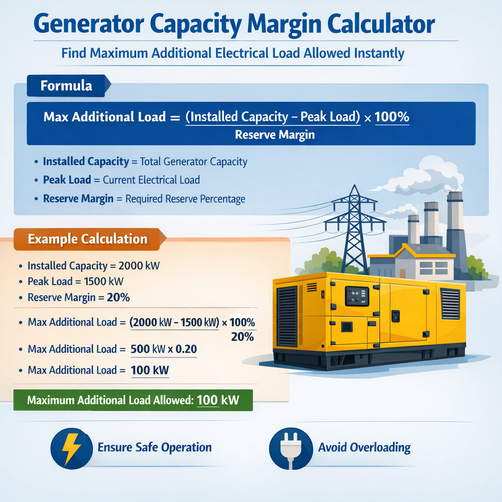
Generator Capacity Margin Calculator – Maximum Additional Electrical Load Allowed
Fundamental concepts for generator capacity margin
Capacity margin is the quantifiable spare electrical capacity that a generator or generator bank can deliver above current peak demand without violating operational limits.
Determining the maximum additional load allowed instantly requires combining nameplate data, derating factors, and current measured load.
Key definitions
- Nameplate rating (kW or kVA): Manufacturer rated continuous output under specified conditions.
- Available capacity (kW): Nameplate adjusted for service factor, derating (altitude, temperature), and reserved capacity.
- Peak load (kW): Measured or forecast highest instantaneous demand to be served by the generator(s).
- Maximum additional load (kW): Spare capacity in kW that can be taken on instantly without exceeding limits.
- Capacity margin (%): Expressed relative to peak load or available capacity; two common definitions are provided.
- Power factor (pf): The ratio of real power (kW) to apparent power (kVA) used when converting kVA ratings to kW.
Primary formulas and variable explanations
Below are the primary formulas used in a Generator Capacity Margin Calculator. Each formula is provided using plain HTML expressions, followed by explanations of each variable and typical values.
Formulas
Available Capacity (kW) = Nameplate Rating (kVA) × Power Factor × Service Factor × Derating Factor − Reserved Capacity (kW)
Variable explanations and typical values
- Nameplate Rating (kVA): Typical commercial generator sizes include 20 kVA, 50 kVA, 100 kVA, 250 kVA, 500 kVA, 1000 kVA. Use manufacturer data.
- Power Factor (pf): Typical pf = 0.8 (industrial motors) to 1.0 (pure resistive). Use pf = 0.8 for kVA→kW conversion if not specified.
- Service Factor (SF): Many generators allow short-term overload; SF typically 1.0 to 1.15. Use 1.0 for continuous rating, 1.1 for short-duration allowances if manufacturer permits.
- Derating Factor: Combined multiplier for altitude, ambient temperature, fuel quality, and maintenance condition. Typical values range 0.75–1.00.
- Reserved Capacity (kW): Capacity held for automatic loads, system critical functions, or safety margins. Typical reserved values 5–20% of available capacity.
- Peak Load (kW): Measured instant demand; for planning use 15-minute average or highest instantaneous value recorded.
Practical derating factors and common conditions
Environmental and operational derates reduce the theoretical nameplate output. Typical derating contributors and approximate values are shown in the table below.
| Condition | Typical Multiplier | Notes |
|---|---|---|
| Standard reference (25°C, sea level) | 1.00 | Manufacturer rating basis unless otherwise stated |
| Ambient temperature 35°C | 0.95–0.98 | Depends on cooling system; OEM curves recommended |
| Ambient temperature 45°C | 0.90–0.95 | High ambient requires derating; consider 0.90 for conservative design |
| Altitude 1,000 m (3,281 ft) | 0.95 | Air density reduction; use OEM altitude correction |
| Altitude 2,000 m (6,562 ft) | 0.90 | Significant derate for combustion engines |
| Fuel quality (diesel; lower cetane) | 0.98–1.00 | Poor fuel can reduce performance marginally |
| Maintenance / aging | 0.95–0.98 | Neglected units produce less than nameplate |
| Parallel operation inefficiencies | 0.99 | Electrical losses and control margin when paralleling multiple units |
Step-by-step calculation method for a practical calculator
- Collect inputs:
- Nameplate rating (kVA) for each generator.
- Power factor to use (default 0.8 if unknown).
- Service factor (1.0 continuous; higher if short-duration allowed).
- Derating multipliers for temperature, altitude, fuel, and maintenance.
- Reserved capacity (kW) required for automatic loads or safety buffer.
- Measured current peak load (kW).
- Compute available capacity for each unit:AvailableCapacity_unit = Nameplate_kVA × pf × SF × Derating
- For banks, sum available capacities:Total Available Capacity = Σ AvailableCapacity_unit − Total Reserved Capacity
- Compute maximum additional load instantly:MaxAdditionalLoad = Total Available Capacity − Peak Load
If MaxAdditionalLoad ≤ 0, no additional load can be accepted without shedding or starting additional units.
- Compute reserve margins:Reserve Margin (%) = ((Total Available Capacity − PeakLoad) / PeakLoad) × 100Capacity Utilization (%) = (PeakLoad / Total Available Capacity) × 100
- Apply operational limits:
- Check generator thermal limits, excitation / AVR limits, and fuel system capability for sustained additional load.
- If the addition is transient, check permissible overload time relative to manufacturer's overload curves.
Extensive common generator size table with typical available capacity examples
This table lists common nameplate sizes, assumed power factor, conservative service factor, a combined derating factor, and resulting available capacity in kW. Use as a starting reference; always verify with OEM data.
| Nameplate (kVA) | Power Factor (pf) | Service Factor (SF) | Derating Factor | Reserved Capacity (%) | Available Capacity (kW) — example |
|---|---|---|---|---|---|
| 20 | 0.8 | 1.00 | 0.98 | 10% | 20 × 0.8 × 1.00 × 0.98 = 15.68 → −10% reserved → 14.11 kW |
| 50 | 0.8 | 1.00 | 0.96 | 10% | 50 × 0.8 × 1.00 × 0.96 = 38.40 → −10% reserved → 34.56 kW |
| 100 | 0.8 | 1.00 | 0.95 | 10% | 100 × 0.8 × 1.00 × 0.95 = 76.00 → −10% reserved → 68.40 kW |
| 250 | 0.8 | 1.00 | 0.92 | 8% | 250 × 0.8 × 1.00 × 0.92 = 184.00 → −8% reserved → 169.28 kW |
| 500 | 0.8 | 1.00 | 0.90 | 5% | 500 × 0.8 × 1.00 × 0.90 = 360.00 → −5% reserved → 342.00 kW |
| 1000 | 0.8 | 1.00 | 0.88 | 5% | 1000 × 0.8 × 1.00 × 0.88 = 704.00 → −5% reserved → 668.80 kW |
Two detailed worked examples with full solutions
Example 1 — Single generator, immediate additional load allowed
Scenario: A 250 kVA standby diesel generator serves a small commercial site. Measured peak load currently is 140 kW. Determine the maximum instantaneous additional load that can be accepted safely.
Given data and assumptions:
- Nameplate rating = 250 kVA
- Assumed power factor = 0.8 (typical for mixed loads)
- Service factor = 1.0 (continuous operation)
- Ambient conditions: 30°C and altitude 200 m → combined derating factor assumed 0.94
- Reserved capacity for EMS/autostart and critical circuits = 10% of available capacity
- Peak load = 140 kW (measured)
Step 1 — Compute raw available capacity (before reserved capacity):
Step 2 — Subtract reserved capacity (10%):
Step 3 — Compute maximum additional load instantly:
Step 4 — Compute reserve margin relative to peak:
Operational notes and checks:
- 29.2 kW additional capacity is available instantly. If the proposed load is transient or motor-starting, consider inrush current and voltage dip; the generator may handle current kW but still have transient voltage/stability limits.
- Verify engine governor response and AVR stability for sudden step load increases. Short-term overload capability may allow temporary increases above 169.2 kW, but only per manufacturer overload curves.
Example 2 — Parallel generator bank and N+1 planning
Scenario: A data center uses two identical 500 kVA generators in parallel (G1 and G2) to supply critical load. One generator must be capable of carrying load if the other fails (N+1). Determine maximum additional instantaneous load allowed while both units are online and whether the system meets N+1 for a projected peak of 620 kW.
Given data and assumptions:
- Two units: each Nameplate = 500 kVA
- Power factor (pf) = 0.9 (power factor correction or largely resistive/electronic loads)
- Service Factor = 1.0 (continuous)
- Derating factor per unit = 0.90 (site altitude and high ambient combined)
- Reserved capacity = 5% of total available capacity
- Current peak load = 620 kW
Step 1 — Compute available capacity per unit:
Step 2 — Total available capacity with both online:
Step 3 — Subtract reserved capacity (5% of total):
Step 4 — Compute maximum additional instantaneous load while both online:
Step 5 — Evaluate N+1 (one unit out):
If one generator fails, remaining single-unit available capacity = Available_per_unit − reserved allocation for single-unit condition.
Conservative check: assign all reserved capacity to remain available during single-unit operation; simpler method: compute single-unit net capacity = 405.00 − (ReservedCapacity_total / 2) = 405.00 − 20.25 = 384.75 kW (approximate)
Because the data center requires the ability to carry the full load on one generator for N+1:
Single-unit net capacity (384.75 kW) < 620.00 kW → N+1 requirement NOT satisfied.
Alternate N+1 calculation (true N+1 check): A single generator must be able to supply the entire load; since one unit rated at 405 kW raw cannot provide 620 kW, N+1 is not met.
Operational recommendations:
- Add a third generator or increase individual unit sizes so that a single unit can support the full critical load.
- Implement load shedding schemes prioritizing noncritical loads during single-unit operation.
- Consider starting an auxiliary generator or connecting to grid supply for redundancy.
Transient behavior, motor starts, and inrush considerations
Maximum additional load in kW does not fully capture dynamic constraints. Motor starting currents, harmonic distortion, and control stability must be assessed.
- Inrush current: Large motors can draw 4–8× locked-rotor current. Ensure generator transient response and AVR can maintain voltage during starts.
- Short-term overload capability: Many diesel gensets permit 10%–20% overload for limited minutes; check manufacturer curves before allowing transient loads.
- Voltage dip thresholds: Sensitive electronics may trip at voltage dips; coordinate soft-starts, VFD settings, and generator AVR parameters.
Practical rule-of-thumb for motor starting on generators
When evaluating an additional load that includes motor starts, estimate the starting kVA, and compare to generator short-term kVA capability:
Ensure generator can support sum of running kW plus simultaneous starting kVA without voltage dropping below tolerated limits.
Implementation details for an online calculator
An automated Generator Capacity Margin Calculator should implement the following logical steps and validation checks to produce safe, conservative results.
- Input validation:
- Ensure nameplate, pf, and derating numbers are numeric and within realistic ranges.
- Provide default suggestions and OEM lookup tables for common models.
- Derating aggregation:
- Multiply environmental multipliers together rather than summing percentages to avoid overstating capacity.
- Allow user to input OEM-specific altitude/temperature curves for precision.
- Reserve policy:
- Allow configurable reserved capacity policies (fixed kW, percentage, or policy-based minimal reserve for safety).
- Transient modelling:
- Include a motor starting module to simulate locked-rotor events and ramp times.
- Allow simulation of simultaneous start events, cold-engine behavior, and fuel limitations.
- Output:
- Display MaxAdditionalLoad (kW), Reserve Margins (%), Capacity Utilization, and recommended operational actions.
- Provide warnings when maximum additional load is negative or below safe thresholds.
Standards, regulations, and authoritative references
Relevant standards and authoritative guidance should be consulted when performing capacity margin calculations and implementing changes to generator loading strategies.
- NFPA 110 — Standard for Emergency and Standby Power Systems: provides requirements for performance and testing of emergency power systems. https://www.nfpa.org/
- IEEE Std 446 — IEEE Recommended Practice for Emergency and Standby Power Systems for Industrial and Commercial Applications (also known as the IEEE Orange Book). Refer for design and sizing practices. https://standards.ieee.org/
- IEC 60034 — Rotating electrical machines: for generator ratings and testing methodologies. https://www.iec.ch/
- NERC Reliability Standards — applicable for utilities and large interconnected systems regarding capacity margins and reserve requirements. https://www.nerc.com/
- Manufacturer generator manuals and datasheets — the definitive source for derating charts, overload curves, and ambient/altitude corrections (e.g., Caterpillar, Cummins, MTU, Kohler).
Operational tips and best practices
- Always verify nameplate assumptions with on-site measurements and OEM data.
- Implement conservative derating for aged equipment or uncertain environmental conditions.
- Use time-stamped SCADA or power monitoring system data to determine true peak values rather than momentary transients unless transients are the target metric.
- Document reserved capacity policies and control logic for safe automatic load acceptance.
- Periodically test under controlled conditions to validate calculated margins, including motor start tests and sustained overload tests within OEM limits.
Examples of common pitfalls and how to avoid them
- Relying solely on nameplate kVA without converting to kW using correct power factor.
- Always convert kVA to kW with actual pf or conservative default.
- Neglecting altitude/temperature effects that reduce combustion engine performance.
- Apply OEM altitude and temperature correction curves.
- Ignoring transient constraints (voltage dip, AVR response) when adding motors or nonlinear loads.
- Simulate or test motor starts under generator supply conditions.
- Misallocating reserved capacity inconsistently across units when paralleling.
- Define reserved capacity centrally and apply it consistently in calculator logic.
Appendix — Quick reference formulas and implementation checklist
Quick formulas:
Implementation checklist for engineers:
- Collect nameplate and OEM derating curves.
- Measure actual peak load using a calibrated power meter.
- Decide service and safety factors (continuous vs. short-term overload).
- Calculate available capacity and maximum additional load.
- Validate with transient analysis for motor starts and inrush.
- Document decisions, safety margins, and operational procedures.
References and further reading
- NFPA 110: Standard for Emergency and Standby Power Systems. National Fire Protection Association. https://www.nfpa.org/
- IEEE Std 446: IEEE Recommended Practice for Emergency and Standby Power Systems. IEEE Standards Association. https://standards.ieee.org/
- IEC 60034: Rotating electrical machines. International Electrotechnical Commission. https://www.iec.ch/
- NERC: North American Electric Reliability Corporation — reliability standards and planning guidelines. https://www.nerc.com/
- Manufacturer technical manuals (example: Cummins Power Generation — Generator Set Technical Manual). Refer to your generator OEM for specific derating charts.
Using the formulas, tables, and worked examples above, engineers and operators can implement a Generator Capacity Margin Calculator to determine the maximum additional electrical load allowed instantly while maintaining safe and compliant operation. Always corroborate calculator outputs with manufacturer limits and regulatory guidance before making operational changes.