This technical guide explains input-based NFPA 70E arc flash PPE level selection quickly and accurately.
Engineers, safety professionals, and electricians will learn calculation steps, tables, and compliance considerations for installations.
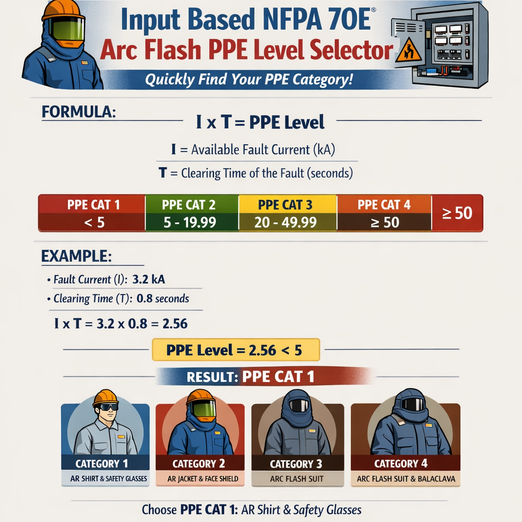
NFPA 70E Arc Flash PPE Category Selector Based on Incident Energy Input
Scope and objective of the input-based PPE level selector
This article provides a practical, input-driven method to identify NFPA 70E PPE categories quickly. It combines parameter definition, lookup workflows, representative tables, formula relationships, and worked examples. The content stresses that final compliance requires a formal arc flash study and professional engineering validation under NFPA 70E and IEEE 1584.
Key input parameters and their technical meaning
An accurate PPE category selection requires a consistent set of input parameters. Capture these values at the equipment point of work and keep units explicit.
- System voltage (line-to-line or line-to-ground) — expressed in volts (e.g., 480 V).
- Available bolted three-phase fault current (Ibf) — in kiloamperes (kA) at the point of fault.
- Protective device clearing time (t) — seconds (s) or cycles; use device operating curves or manufacturer data.
- Working distance (D) — measured from the arc-source plane to the worker’s torso, in inches or millimeters.
- Equipment enclosure characteristics and grounding — influence arcing current and energy coupling (enclosed vs open, grounded neutral, ventilation).
- Task type and exposure duration — influences selection of additional protective items beyond clothing (face shield, balaclava, HRC-rated tools).
Regulatory and normative frame
Use NFPA 70E and IEEE 1584 as primary normative references for arc flash risk assessment and incident energy calculation. NFPA 70E requires either an incident-energy analysis or a documented demonstration that PPE selected by a table method is appropriate.
- NFPA 70E — Electrical Safety in the Workplace: https://www.nfpa.org/70E
- IEEE Std 1584 — Guide for Performing Arc-Flash Hazard Calculations (2018 edition): https://standards.ieee.org/standard/1584-2018.html
- OSHA arc flash information and interpretation: https://www.osha.gov/arc-flash
General calculation methodology (workflow)
- Collect measured or calculated bolted fault current (Ibf) at the equipment terminal using short-circuit analysis or utility information.
- Determine the expected arcing current (Iarc). This is usually less than bolted fault current and depends on equipment geometry and fault type.
- Obtain protective device clearing time (t) for the given fault magnitude from device trip curves or instantaneous/short-time settings.
- Choose working distance (D) appropriate for the task (commonly 18 in (457 mm) for switchgear/front-of-board work, 24 in (610 mm) for some panel tasks).
- Perform an incident energy calculation (when performing an arc flash study) or use a validated lookup table adapted to the inputs for a quick PPE category selection.
- Map computed or estimated incident energy to a PPE category using NFPA 70E ATPV thresholds and garment assemblies.
Formula relationships and variable explanation
Incident energy is a function of arcing current, fault duration, geometry (distance, enclosure), and coupling factors. Use validated empirical models (IEEE 1584) for precise results. The relationships below show the dependencies, variables and typical ranges. These are explanatory; do not substitute them for a formal arc flash study.
Representative formula relationships
Generic proportional relationship (conceptual):
E ∝ I_arc × t / D^2
Where:
- E = incident energy at worker location (cal/cm^2)
- I_arc = arcing fault current (kA)
- t = arcing fault duration (s)
- D = working distance (inches or mm; be consistent)
Practical incident energy calculation must use the IEEE 1584 empirical model or equivalent validated software. The model produces a numeric E from measured inputs; the proportional expression above describes the physics qualitatively: energy increases with higher I_arc and longer clearing times, and decreases rapidly with increased distance.
Variable typical values and notes
- I_arc (typical) = 2 kA to 50 kA depending on system voltage, fault impedance, and geometry.
- t (typical) = 0.01 s to 0.5 s (10 ms to 500 ms) depending on relay/trip curves, fuse characteristics, and clearing coordination.
- D (typical) = 12 in (305 mm) for close-in tasks to 36 in (914 mm) for more distant work.
- Note: ATPV values are expressed in cal/cm^2 and define fabric protective levels tested per ASTM F1959/F1959M or NFPA 2112 where appropriate.
Practical PPE category mapping (typical ATPV thresholds)
Below is a widely-used mapping between PPE category numbers and minimum arc rating (ATPV). These thresholds are commonly quoted in arc-flash guidance. Confirm and apply the ATPV values that are current in the edition of NFPA 70E adopted by your jurisdiction.
| PPE Category | Approximate Minimum ATPV (cal/cm^2) | Typical Arc-Rated Garment System | Common use-case |
|---|---|---|---|
| 0 | < 1.2 | Non-melting HRC-rated basic protection (FR shirt/jeans may not be sufficient) | Very low energy tasks (observational work with boundary) |
| 1 | 4 | FR shirt and pants, arc-rated face shield or balaclava, hearing protection | Light equipment operations, testing with low incident energy |
| 2 | 8 | Arc-rated jacket/coverall or FR shirt/pants with ARC-rated clothing; arc hood optional | Routine front-of-equipment work with moderate fault currents |
| 3 | 25 | Arc flash suit jacket, arc pants, arc hood, gloves | High-energy tasks such as bus work, live parts operations |
| 4 | 40+ | Arc flash suit full body, hood with face shield, insulated tools and gloves | Extreme energy exposures; only for critical operations with engineered controls |
Input-based PPE selector table (adapted examples)
The following lookup is an adapted, illustrative selector table keyed to three-phase low-voltage enclosed equipment at a working distance of 18 inches. It maps ranges of available bolted fault current and clearing times to a suggested PPE category for quick screening. This table is illustrative; always validate with a formal study.
| Available Bolted Fault Current (kA) | Clearing Time (s) | Estimated PPE Category (18 in) | Notes |
|---|---|---|---|
| 0 – 5 | <= 0.02 | 0 – 1 | Low energy; task-dependent |
| 0 – 5 | 0.02 – 0.10 | 1 | Short clearing time keeps incident energy low |
| 5 – 10 | <= 0.05 | 1 – 2 | Moderate energy; choose higher category with longer t |
| 10 – 20 | 0.02 – 0.20 | 2 – 3 | Common for many 480 V systems; verify with calculation |
| 20 – 35 | 0.02 – 0.20 | 3 | High incident energy; consider work planning and boundaries |
| >35 | any | 3 – 4 | Extreme energies frequently exceed table methods; engineering evaluation required |
Selector algorithm (step-by-step quick method)
- Input system voltage, available bolted fault current (Ibf), clearing time (t), working distance (D).
- If you have an established conversion factor for arcing current (Iarc = k × Ibf), apply it. Typical k values vary with equipment; use conservative k (e.g., 0.6–0.9) for enclosed low-voltage switchgear when specific geometry is unknown.
- For rapid screening, use the adapted selector table above keyed to Ibf and t at standard D = 18 in. If D differs, err on the side of higher protection (reduce D increases energy).
- If the estimated PPE category is ≥3 or fault currents are >35 kA, schedule a formal incident energy study per IEEE 1584 and implement engineered controls.
- Document assumptions (Ibf source, protective device curve, working distance, arcing current factor) for traceability and audit compliance.
Worked examples (illustrative, follow-up study required)
Example 1 — 480 V switchgear, bolted fault at bus = 22 kA, automatic upstream breaker
Scenario inputs:
- Voltage: 480 V three-phase
- Available bolted fault current (Ibf): 22 kA at the bus
- Protective device: upstream breaker instantaneous trip clears in 0.08 s at this fault magnitude
- Working distance (D): 18 inches (457 mm)
- Equipment: enclosed switchgear with typical arcing characteristics
Step 1 — Estimate arcing current (conservative):
Step 2 — Quick table-based PPE category selection (use adapted selector table):
- Ibf = 22 kA falls in the 20–35 kA band;
- t = 0.08 s lies in the 0.02–0.20 s band;
- Selector table recommends PPE Category 3 for this band at 18 in working distance.
Step 3 — Map to clothing and ATPV:
- PPE Category 3 typical ATPV = 25 cal/cm^2;
- Recommended ensemble: arc flash suit jacket and pants or arc suit, arc hood with face shield rated ≥25 cal/cm^2, arc-rated gloves, hearing protection, leather outerwear as required.
Step 4 — Compliance note:
- This is a screening estimate. Because calculated exposure falls in Category 3, perform a formal incident energy analysis per IEEE 1584 to confirm the incident energy value and required ATPV; then record results in the arc flash risk assessment and labeling.
Example 2 — 480 V motor control center (MCC), bolted fault at feeder = 8 kA, fused feeder protective device
Scenario inputs:
- Voltage: 480 V three-phase
- Available bolted fault current (Ibf): 8 kA at the feeder
- Protective device: fast-acting fuse that clears the fault in 0.02 s
- Working distance (D): 18 inches
- Equipment: MCC cubicle with small enclosure opening
Step 1 — Estimate arcing current:
Step 2 — Table-based selection:
- Ibf = 8 kA corresponds to the 5–10 kA band;
- t = 0.02 s is ≤ 0.05 s band;
- Selector table indicates PPE Category 1 to 2 for these values; the faster clearing time and lower current suggest Category 1.
Step 3 — Map to clothing and ATPV:
- PPE Category 1 typical ATPV = 4 cal/cm^2;
- Recommended clothing: FR shirt and pants or FR coverall with arc-rated face protection rated ≥4 cal/cm^2, plus gloves and hearing protection.
Step 4 — Documentation and verification:
- Record assumptions (k factor, fuse clearing time). If access to manufacturer’s fuse time-current curves or measured trip times is possible, refine t and repeat selection. If incident energy from a formal study shows >4 cal/cm^2, upgrade PPE accordingly.
Operational considerations, engineering controls and controls hierarchy
PPE is the last line of protection. The hierarchy of controls applies equally to arc flash hazard mitigation:
- Elimination: De-energize equipment prior to work when feasible per NFPA 70E 120.5 and lockout/tagout.
- Engineering controls: Install current-limiting devices, arc-resistant switchgear, arc blast mitigation, and root cause reduction measures.
- Administrative controls: Work procedures, limited access, hot-work permits, and job briefings to minimize exposure time and duty cycles.
- PPE: Use correctly rated arc-rated garments and accessories, with proper fit, inspection, and maintenance.
Labeling and documentation for compliance
When an arc flash study exists, equipment must be labeled per NFPA 70E with incident energy or PPE category and the working distance used for evaluation. Essential label fields:
- Nominal system voltage
- Arc flash boundary distance
- Incident energy (cal/cm^2) and corresponding working distance, OR PPE category if allowed
- Minimum required PPE (concise clothing assembly)
- Date of study and engineer contact
Verification, testing and periodic review
Arc flash hazard assessments and PPE assignments must be reviewed when system changes occur: modifications, fault current changes (utility contributions), protective device replacements, or changes in task/work distance.
- Recalculate incident energy after any major equipment change.
- Retain time-current curves and short-circuit calculations with the arc flash report.
- Conduct training and fit-testing of PPE and document user competency.
Limitations and safety caveats
- Quick lookup methods are screening tools only. They do not replace comprehensive arc flash studies using IEEE 1584 or equivalent validated engineering models.
- Assumed arcing current factors (k) and clearing times must be conservative. Underestimating either risks under-protection.
- PPE must be selected with margin and consider multi-layer systems, layering effects, and potential for debris or melting materials.
Best practices for field application of the input-based selector
- Always capture source and date for the bolted fault current (Ibf) — utility or calculated data.
- Use manufacturer time-current curves or relay settings to derive conservative clearing times for the expected fault magnitude.
- When using lookup tables, prefer the nearest higher category if any input is uncertain.
- Label equipment per NFPA 70E and include working distance used and ATPV requirements.
- Archive calculations and assumptions for revalidation after system changes.
References and authoritative resources
- NFPA 70E — Standard for Electrical Safety in the Workplace. National Fire Protection Association. https://www.nfpa.org/70E
- IEEE Std 1584 — Guide for Performing Arc-Flash Hazard Calculations. IEEE Standards Association. https://standards.ieee.org/standard/1584-2018.html
- OSHA — Electrical, general industry citations and guidance, arc flash information. https://www.osha.gov/arc-flash
- ANSI/IEEE technical papers and manufacturer application notes for fuse clearing times and breaker trip curves (consult manufacturer websites for device-specific curves).
Final recommended workflow for practitioners
- Collect accurate baseline inputs: voltage, available fault current at point-of-work, device characteristics, and working distance.
- Use the input-based selector for rapid screening and immediate work planning when a full arc-flash study is not yet available.
- For any estimated PPE category ≥2 or when Ibf > 10 kA, prioritize scheduling a full incident energy analysis per IEEE 1584 and update labels and PPE lists accordingly.
- Document all assumptions, provide training for workers, and enforce safe work practices including de-energization where practical.
This article presents an input-driven, pragmatic approach to find PPE categories quickly and consistently. Remember: quick selection aids immediate hazard mitigation planning but does not substitute for a detailed arc flash study and licensed professional review required for formal NFPA 70E compliance.