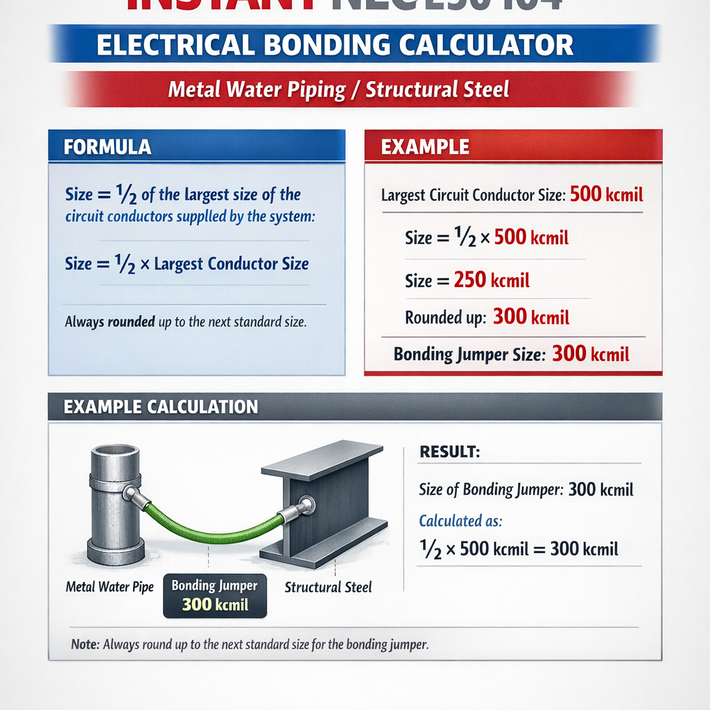
Instant NEC 250 calculator for electrical bonding of metal water piping and structural steel systems.
This guide provides calculation procedures, code references, examples, and recommended conductor sizes accurately for complianceNEC 250.104 Instant Bonding Size Calculator — Equipment Grounding Conductor for Metal Water Piping & Structural Steel
Scope, objective, and regulatory context
This article explains how to size and verify electrical bonding conductors for metal water piping and structural steel in compliance with NEC 250. It focuses on practical calculation methods, typical conductor data, and worked examples that can be used by engineers and installers to confirm compliance with bonding requirements and ensure effective fault current return paths.
Fundamental definitions and code relationships
Bonding vs. grounding (earthing) — technical distinction
- Bonding: Creating an electrically continuous path between conductive parts to ensure low-impedance fault current flow and maintain equipotential conditions.
- Grounding (earthing): Connection of electrical conductors to earth to limit voltage to earth and establish a reference for protective devices.
- NEC context: Bonding ensures exposed conductive parts and conductive systems (e.g., metal water piping, structural steel) are tied to the grounding electrode system per NEC 250.*
NEC sections most relevant to this topic
- NEC 250.52 — Grounding Electrode System (identifies metal underground water pipe as an electrode when in contact with earth for 10 ft or more).
- NEC 250.66 — Size of grounding electrode conductor and bonding jumpers where required (prescriptive sizing guidance).
- NEC 250.104 — Bonding requirements for piping and other systems (bonding metal water piping and structural steel where likely to become energized).
- NEC 250.122 — Equipment grounding conductor sizing for circuits and branch-circuit equipment grounding conductors.
Design principles for bonding metal water piping and structural steel
When bonding is required
- Metal water piping that is likely to become energized must be bonded to the service grounding electrode system or equipment grounding conductor.
- Metal underground water pipe that is in direct contact with earth for 10 ft or more is also a grounding electrode (NEC 250.52).
- Structural steel that serves as a conductor or is likely to become energized must be bonded to the grounding electrode system or the equipment grounding conductor.
Permitted bonding methods
- Direct connection to the grounding electrode conductor (GEC) or service equipment grounding terminal with a bonding jumper sized per NEC prescriptions.
- Equipotential bonding via a bolted or welded connection meeting NEC requirements for electrical continuity and corrosion protection.
- Use of listed bonding clamps and connectors where required for water piping and structural steel interconnections.
Sizing methodology — prescriptive and analytical approaches
NEC provides prescriptive tables and rules to size bonding and grounding conductors. Two approaches are commonly used:
- Prescriptive (NEC table-based): Select the minimum conductor size from tables such as 250.66 and 250.122, keyed to the rating of the overcurrent protective device (OCPD) protecting the circuit or service.
- Analytical (circuit/impedance-based verification): Compute conductor resistance and verify that fault current will be sufficient and that protective device clearing times meet safety criteria. This approach supplements prescriptive sizing for unusual installations or long runs.
Key prescriptive rule (summary)
Where metal water piping or structural steel must be bonded, the bonding jumper shall not be smaller than the grounding electrode conductor required by NEC 250.66 or the equipment grounding conductor required by NEC 250.122, whichever applies. Use the largest relevant OCPD when sizing for the service or feeder.
Electrical properties and formulas used in analytical verification
Analytical verification uses basic conductor electrical properties to confirm effectiveness:
- R = resistance (ohms)
- ρ = electrical resistivity of conductor material (ohm·m). For copper at 20 °C, ρ ≈ 1.724 × 10⁻⁸ Ω·m.
- L = length of conductor (meters)
- A = cross-sectional area (m2)
- V = voltage across the bonding conductor during fault (volts)
- I = prospective fault current (amperes)
- R = conductor resistance (ohms)
Energy (I2t) during clearing: I2t = ∫ I(t)2 dt over clearing time
- Used to assess heating of the conductor during short-circuit events and to verify thermal withstand.
Typical units and conversions often used:
- 1 AWG size corresponds to a cross-sectional area in mm2 (see AWG table below).
- Length units: convert feet to meters by multiplying by 0.3048.
- Resistance per unit length can be taken from standard tables or calculated from resistivity and area.
Common conductor data and reference table
| AWG / Size | Area (mm²) | Diameter (mm) | Approx. R (Ω/1000 ft @20°C) | Typical Used For (example) |
|---|---|---|---|---|
| 14 AWG | 2.08 | 1.63 | 2.575 | 15 A branch-circuit EGC |
| 12 AWG | 3.31 | 2.05 | 1.588 | 20 A branch-circuit EGC |
| 10 AWG | 5.26 | 2.59 | 0.999 | 30 A branch-circuit EGC |
| 8 AWG | 8.37 | 3.26 | 0.628 | 60 A EGC/100 A GEC in some installations |
| 6 AWG | 13.3 | 4.11 | 0.395 | 60–100 A equipment grounding or feeders |
| 4 AWG | 21.15 | 5.19 | 0.2485 | Common GEC for 200 A services |
| 2 AWG | 33.62 | 6.54 | 0.1563 | Large services, feeders |
| 1/0 AWG | 53.5 | 9.27 | 0.0983 | 400 A service GEC candidate |
| 2/0 AWG | 67.4 | 10.4 | 0.0780 | Large service and grounding |
Notes: R values are approximate conductor DC resistances per 1000 ft at 20 °C. Use manufacturer data for final verification and consider temperature correction for fault conditions.
Prescriptive conductor sizing reference (typical values)
The following table provides typical industry practice example sizes for copper bonding/grounding conductors relative to service or feeder OCPD ratings. Always verify against the current NEC tables (250.66, 250.122, and local amendments).
| Service/Feeder OCPD (A) | Common Minimum Copper GEC/Bonding Jumper (typical) | Common EGC for Branch Circuits |
|---|---|---|
| 100 A | 8 AWG Cu (common in older/limited installs; verify table) | 8 AWG for 60 A, 10 AWG for 30 A circuits |
| 200 A | 4 AWG Cu (very common) | 6 or 8 AWG depending on circuit |
| 400 A | 2/0 or 1/0 AWG Cu (varies, check NEC 250.66) | Large feeders sized accordingly |
| 600 A | 1/0 AWG Cu or parallel conductors (project dependent) | Engineered |
These entries are guidance only; NEC tables are authoritative. Where ambiguity exists, follow the NEC table values or consult the AHJ.
Calculation examples — worked cases
Example 1 — Bonding metal water piping to a 200 A service
Scenario: A commercial building has a 200 A main service. Metal water piping (in direct contact with earth less than 10 ft) runs into the building and must be bonded to the grounding electrode system at the service equipment. The distance from service equipment to the bonding point on the water pipe is 30 ft (one-way conductor run). The installer chooses a copper bonding jumper sized per typical NEC practice.
Step 1 — Select prescriptive conductor size
Typical practice and NEC guidance: For a 200 A service many installations use 4 AWG copper as the grounding electrode conductor / bonding jumper minimum. Confirm with NEC 250.66 table in the applicable edition.
Step 2 — Analytical check: compute DC resistance of 4 AWG over the run
Use R = ρ × L / A or use tabulated R per length. Using the tabulated approximate DC resistance: R_1000ft ≈ 0.2485 Ω per 1000 ft for 4 AWG copper.
Length (one-way) = 30 ft; round-trip length for fault return path typically considered 2 × 30 ft = 60 ft (for voltage drop/resistance estimate).
Step 3 — Evaluate expected voltage during fault (example prospective fault current)
Assume a conservative prospective available fault current at the service of I_sc = 10,000 A (this depends on utility/source impedance and transformer). Then
This voltage is across the bonding path during fault. The protective device clearing time and impedance path govern safety. This illustrative calculation indicates that while R is low, significant voltage can exist; however the prescriptive sizing (4 AWG) is intended to ensure low impedance and adequate fault current flow to operate overcurrent protection.
Step 4 — Documentation and installation notes
- Install 4 AWG copper bonding jumper between metal water piping and service grounding terminal using listed clamps.
- Ensure mechanical protection of the jumper where exposed and verify connections are accessible for inspection.
- Record GEC routing, clamp type, and length in as-built drawings and provide photos to AHJ for acceptance.
Example 1 — Detailed solution summary
- Prescriptive conductor: 4 AWG Cu (typical for 200 A service) — confirm NEC 250.66 for edition in force.
- Calculated round-trip resistance for 60 ft: ≈ 0.0149 Ω.
- At 10 kA fault: voltage across bonding conductor ≈ 149 V (illustrative); conductor selection per NEC ensures adequate fault clearing via service overcurrent protective device.
Example 2 — Bonding structural steel to service grounding electrode on a 400 A service
Scenario: A renovation requires bonding of a building’s primary structural steel framework to the service grounding electrode system. The service OCPD is 400 A, and the connection point at the main service is 50 ft from the nearest connection point on structural steel. The steel itself is not continuous to earth and must be bonded for safety.
Step 1 — Prescriptive selection
Typical guidance: For a 400 A service the grounding electrode conductor/bonding jumper selection frequently uses 2/0 AWG Cu or 1/0 depending on the NEC table and conductors present. For this example, select 1/0 AWG Cu as a conservative typical value; verify against the current NEC 250.66.
Step 2 — Compute resistance for verification
Approximate R_1000ft for 1/0 AWG Cu ≈ 0.0983 Ω/1000 ft (from table above).
Round-trip length = 2 × 50 ft = 100 ft.
Step 3 — Expected behavior under fault
Assume available fault current I_sc = 25,000 A (large service/transformer supplying the building). Then V ≈ I × R = 25,000 × 0.00983 ≈ 245.8 V across run during fault. Again, the prescriptive sizing ensures the fault current path is low-impedance enough to operate the protective device.
Step 4 — Installation and connection details
- Make positive connection to structural steel by welding or bolted connection verified for electrical continuity; if using bolted connections, use listed bonding clamps and remove paint/coating at contact area per manufacturer instructions.
- Install 1/0 AWG Cu bonding jumper, secure routing to avoid mechanical damage, and protect where subject to corrosion or physical damage.
- Record the bonding path, conductor size, connection method, and test continuity.
Example 2 — Detailed solution summary
- Selected bonding conductor: 1/0 AWG Cu (typical for 400 A service; verify NEC 250.66).
- Round-trip resistance for 100 ft: ≈ 0.00983 Ω.
- At 25 kA fault, voltage drop ≈ 246 V (illustrative); conductor sized to prescriptive practice to achieve reliable fault clearing via overcurrent protective device.
Practical testing, inspection, and documentation
Field verification checks
- Continuity/resistance testing: Measure resistance between bonded parts and the grounding electrode conductor. Values should be low (milliohms), but no single universal acceptance threshold exists; compare with design and previous installations.
- Visual inspection: Confirm listed clamps, tightness, no paint at contact area, mechanical protection, and proper labeling if required.
- Record keeping: Photograph connections, record conductor sizes, and note lengths for future maintenance and verification.
Special conditions and mitigation
- Long conductor runs: For very long bonding runs, consider upsizing conductors to reduce resistance and potential for step and touch voltages during faults. Analytical assessment and coordination with protective device characteristics is recommended.
- Parallel conductors: Where physically required, parallel bonding conductors may be used if installed per manufacturer and NEC guidance; ensure current division and mechanical continuity are verified.
- Corrosive environments: Use tinned copper, corrosion-resistant fittings, or protective routing when bonding in marine or corrosive environments.
Installation best practices for water piping and structural steel bonding
- Make connections at accessible locations using listed clamps or welds as permitted.
- Provide at least two bonding points for large distributed systems when required by the AHJ or project specifications to minimize single-point failure.
- Where bonding around equipment such as water meters is required, provide bonding jumpers around nonconductive sections per NEC.
- Maintain good mechanical and electrical continuity: clean contact area, use anti-oxidation compound where appropriate per manufacturer, tighten bolts to required torque.
Normative references and further reading
Primary code and engineering references relevant to bonding metal water piping and structural steel:
- NFPA 70, National Electrical Code (NEC): See particularly Article 250 sections (consult the edition adopted by the authority having jurisdiction). Official NFPA site: https://www.nfpa.org/
- IEEE Std 80 — Guide for Safety in AC Substation Grounding (useful for step-and-touch voltage considerations): https://standards.ieee.org/
- UL and manufacturer product listings for bonding clamps and grounding connectors (search on https://www.ul.com for specific listed hardware).
- Local Authority Having Jurisdiction (AHJ) interpretations and amendments — consult local code enforcement for jurisdictional requirements.
Checklist for regulatory compliance and handover
- Confirm the edition of NEC adopted and reference the correct tables (250.66, 250.104, 250.122).
- Document conductor sizes, lengths, and connection points on drawings and in O&M manuals.
- Provide continuity test results and photographs to the AHJ.
- Label bonding conductors and GECs where required and provide route diagrams for maintenance staff.
Frequently asked calculation questions and quick answers
- Q: Can I always size the bonding jumper equal to the equipment grounding conductor? A: Use the larger requirement from NEC tables (250.66 and 250.122) and consider service/feeder context.
- Q: Are welded connections preferable? A: Welding provides low resistance and permanence for structural steel, but bolted connections with listed clamps are acceptable if properly installed.
- Q: When is upsizing required beyond NEC minimum? A: For long conductor runs, high prospective fault current, or to maintain low touch/step voltages, upsizing may be prudent after analytical assessment.
Closing compliance note and professional practice
Apply the prescriptive NEC rules first, then supplement with analytical verification when necessary. Engage the AHJ early for unusual installations, and document the chosen approach thoroughly. For any installation-specific questions, refer to the latest NEC edition and consult a licensed electrical engineer or the AHJ.
External authoritative links
- NFPA — National Fire Protection Association, NEC resources and handbook: https://www.nfpa.org/
- IEEE Standards — grounding and electrical safety standards: https://standards.ieee.org/
- U.S. Occupational Safety and Health Administration (OSHA) — electrical safety resources: https://www.osha.gov/
- UL Product iQ — searchable listings for bonding clamps and connectors: https://iq.ulprospector.com/