This article examines parallel transformer operation compatibility, KVA ratio, Z, and phase shift analysis requirements.
Detailed calculation methods, normative references, and practical examples facilitate correct parallel transformer selection decisions safely.
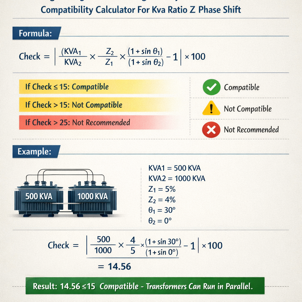
Parallel Transformer Compatibility Calculator (kVA Rating, Impedance, Phase Shift)
Fundamental requirements for transformers to operate in parallel
Parallel operation of transformers requires strict matching of electrical characteristics to avoid circulating currents, unequal load sharing, overheating, and protection nuisance tripping. The primary compatibility conditions are:
- Identical or compatible phase displacement (vector group).
- Voltage ratio (turns ratio) within strict tolerance at the selected tap positions.
- Percent impedance (per-unit Z) referred to a common base that gives acceptable load sharing.
- Similar X/R ratios and impedance angles to avoid circulating reactive sharing differences.
- Transformer polarity and grounding arrangements consistent for safe paralleling.
Key parameters and formulas used in compatibility calculations
Precise calculation uses per-unit impedance conversion and current division relations. All formulas are shown in HTML form and each variable is explained with typical values.
1. Per-unit impedance conversion
Formula to convert a transformer percent impedance from its nameplate rating to a common base:
Z_pu_new = Z_pu_nameplate · (S_base_new / S_nameplate)
Where:
- Z_pu_new = per-unit impedance on the new common power base (pu). Typical range: 0.04 to 0.12 (4%–12%).
- Z_pu_nameplate = nameplate per-unit impedance = Z%_nameplate / 100.
- S_base_new = chosen common power base in VA (e.g., 1500 kVA → 1.5·10^6 VA).
- S_nameplate = transformer rated power in VA as printed on nameplate.
Example typical values: Z%_nameplate = 6.0% → Z_pu_nameplate = 0.06. If S_nameplate = 1000 kVA and S_base_new = 1500 kVA, then Z_pu_new = 0.06 · (1500 / 1000) = 0.09 pu.
2. Current division and load sharing
For two transformers paralleled on the same voltage bus, currents divide approximately inversely proportional to their per-unit impedances referred to the same base. The share of load current taken by transformer 1 is:
I1 = I_total · (Z2_pu / (Z1_pu + Z2_pu))
Where:
- I1 = current in transformer 1 (A).
- I_total = total load current supplied by both transformers (A).
- Z1_pu, Z2_pu = per-unit impedances of transformer 1 and 2 on the same base (pu).
Corresponding apparent power share at rated voltage V_base (line-to-line) is:
S1_share = S_total · (Z2_pu / (Z1_pu + Z2_pu))
Typical practical requirement: the percent deviation from ideal share (based on KVA ratings) should be within ±10% for safe long-term operation.
3. Ideal impedance ratio for proportional kVA sharing
If two transformers are to share load in direct proportion to their nameplate kVA ratings, the needed relation between impedances is:
Z1_pu / Z2_pu = S2 / S1
Where:
- S1, S2 = transformer ratings (kVA).
If the actual ratio differs, the load will be redistributed according to the current division formula. Typical industry practice accepts up to 10% mismatch in load sharing without corrective measures for distribution transformers, tighter for large power transformers.
4. Voltage ratio mismatch and circulating current estimation
If the no-load turns ratio differs slightly, circulating currents can flow even with no external load. A simplified estimate of circulating current caused by ratio mismatch is:
I_circ ≈ V_line / (Z1 + Z2) · (Δa / a)
Where:
- I_circ = circulating current magnitude (A).
- V_line = nominal line voltage (V).
- Z1, Z2 = equivalent series impedances referred to the same voltage (Ω).
- Δa / a = relative turn ratio difference between transformers (unitless), typically expressed as (a1 - a2)/a_avg.
Typical acceptance: ratio mismatch should be kept within manufacturer tolerance (often 0.5% or better) to limit circulating currents to acceptable values.
Practical data tables: common kVA ratings and typical percent impedances
| Transformer Rating (kVA) | Typical Percent Impedance Z% | Typical X/R Ratio | Typical Vector Group (common) |
|---|---|---|---|
| 50 | 4.0 | 10 | Dyn0 / Yy0 |
| 100 | 4.5 | 10 | Dyn0 / Yy0 |
| 250 | 5.5 | 12 | Dyn1 / Yy0 |
| 500 | 6.0 | 12 | Dyn11 / Yy0 |
| 1000 | 6.5 | 13 | Dyn11 / Yy0 |
| 2000 | 7.0 | 13 | Dyn11 |
| 5000 | 8.0 | 14 | Dyn11 |
| Vector Group | Phase Displacement (degrees) | Parallelable With | Notes |
|---|---|---|---|
| Yy0 | 0° | Yy0 | Direct coupling; neutral bonding must match. |
| Dy1 / Dyn1 | ±30° | Dy1, Dyn1 of same sign | Must have identical clock number and polarity. |
| Dy11 / Dyn11 | ±330° (−30°) | Dy11, Dyn11 of same sign | Common for distribution power transformers. |
| Yd5 | 150° or −210° | Only identical vector group | Large phase shifts require identical group to parallel. |
Algorithm for a transformer-parallel compatibility calculator
Implementing a deterministic compatibility calculator follows these steps:
- Collect nameplate data for each transformer: S_nameplate (kVA), Z%_nameplate, rated voltages, vector group, tap position, X/R, polarity.
- Verify vector group exact match or documented compatible group. If not matching, disallow paralleling.
- Check voltage ratio: compute percentage ratio difference at selected taps. If difference exceeds tolerance (typical 0.5%), disallow or recommend tap adjustment.
- Select a common S_base (often the sum of rated kVA or the larger unit rating). Convert Z% to per-unit on this base using Z_pu_new = (Z%_nameplate / 100) · (S_base / S_nameplate).
- Compute current and kVA sharing using S1_share = S_total · (Z2_pu / (Z1_pu + Z2_pu)). Compare to desired proportional sharing S1 / (S1+S2). If deviation exceeds allowable threshold (commonly 10%), present mitigation steps.
- Estimate circulating currents from ratio mismatch and impedance mismatch. If estimated I_circ or S_unequal exceeds design limits, flag for action.
- Provide recommended corrective actions: tap changes, impedance modifications (rare), installation of load-sharing reactors, or avoid paralleling.
Real-case examples with full calculations
Example 1 — Paralleling a 1000 kVA and 500 kVA distribution transformers
Scenario: Two transformers, T1 = 1000 kVA, Z%_1 = 6.5%, vector group Dyn11, and T2 = 500 kVA, Z%_2 = 6.0%, vector group Dyn11. Both are selected for parallel connection on a 11 kV distribution bus. Tap positions are equal. Determine expected load sharing and assess compatibility.
Step 1 — Choose S_base. Use S_base = 1500 kVA (sum): S_base = 1000 + 500 = 1500 kVA.
Step 2 — Convert impedances to per-unit on common base using the formula
Z_pu_new = (Z%_nameplate / 100) · (S_base / S_nameplate)
For T1:
Z1_pu = 0.065 · (1500 / 1000) = 0.065 · 1.5 = 0.0975 pu.
For T2:
Z2_pu = 0.060 · (1500 / 500) = 0.060 · 3.0 = 0.180 pu.
Step 3 — Determine load sharing for a total load of S_total. The share of T1 is:
S1_share = S_total · (Z2_pu / (Z1_pu + Z2_pu))
Compute the ratio factor:
Z2_pu / (Z1_pu + Z2_pu) = 0.180 / (0.0975 + 0.180) = 0.180 / 0.2775 = 0.6486 (64.86%).
Thus T1 will provide 64.86% of S_total while T2 supplies 35.14% of S_total. Compare with ideal proportional share based on ratings:
Ideal T1 share = 1000 / 1500 = 66.67%.
Deviation for T1 = (64.86 − 66.67) / 66.67 = −2.76% relative (well within typical ±10% acceptance).
S1_actual = 1500 · 0.6486 = 972.9 kVA (less than T1 rating 1000 kVA — acceptable).
S2_actual = 1500 · 0.3514 = 527.1 kVA (slightly above T2 rating 500 kVA — not acceptable for continuous operation).
Step 5 — Conclusion and mitigation:
- Although percent impedance difference yields acceptable proportional sharing, T2 would be overloaded by about 5.4% at full combined rated load. Continuous operation at this condition is not recommended.
- Mitigation options: reduce combined loading to safe level, change tap to slightly redistribute impedance (if allowed), or select a larger second transformer, or rebase impedances by paralleling with a modified S_base (not practical) or use an impedance equalizing reactor on the lower-rated unit.
Example 2 — Paralleling two 2000 kVA power transformers with different percent impedances and a vector-group check
Scenario: T3 = 2000 kVA, Z%_3 = 7.0%, vector group Yy0; T4 = 2000 kVA, Z%_4 = 8.5%, vector group Yy0. Both feed a common 66 kV bus via identical taps. Check whether they can be paralleled and compute expected load sharing.
Step 1 — Vector group check: Both Yy0 — phase displacement = 0°, identical, OK.
Step 2 — Choose S_base = 2000 + 2000 = 4000 kVA.
Step 3 — Convert impedances to common base:
Z3_pu = 0.070 · (4000 / 2000) = 0.070 · 2.0 = 0.140 pu.
Z4_pu = 0.085 · (4000 / 2000) = 0.085 · 2.0 = 0.170 pu.
Step 4 — Compute shares using S1_share formula (choose T3 as transformer 1):
Share factor for T3 = Z4_pu / (Z3_pu + Z4_pu) = 0.170 / (0.140 + 0.170) = 0.170 / 0.310 = 0.5484 (54.84%).
S3_actual = 4000 · 0.5484 = 2193.6 kVA — this is 9.68% above its rating (2000 kVA) and therefore unacceptable.
S4_actual = 4000 · 0.4516 = 1806.4 kVA — 9.68% below rating.
Step 5 — Evaluation:
- Identical vector groups mitigate phase shift problems; however, the percent impedance difference leads to T3 being overloaded in full-parallel operation.
- Options: reduce maximum combined load, replace T3 with higher impedance or upgrade T3 rating, insert impedance equalizing reactors, or choose not to operate both simultaneously at full load.
- Since ratings are equal, ideal operation requires Z3_pu = Z4_pu. Here Z3_pu is 17.6% lower than Z4_pu, which creates significant imbalance.
Mitigation techniques and practical recommendations
When compatibility checks identify issues, engineers can consider one or more of the following measures:
- Tap matching: adjust on-load tap changers to equalize voltage ratios within tight tolerances.
- Impedance matching: select or reorder transformers such that their percent impedances on common base are closer.
- Load balancing: use protection and control logic to avoid simultaneous full loading; stagger in-service periods.
- Series reactors or autotransformers: install impedance equalizing reactors on the transformer with lower impedance to reduce its share.
- Transformer replacement: install matched units with identical vector groups, percent impedance, and rated voltage ratio.
Normative references and authoritative sources
Designers and specifiers should consult relevant standards and manufacturer application notes. Key references include:
- IEC 60076-1: Power transformers — Part 1: General — general requirements and tests. See: https://www.iec.ch
- IEEE Std C57.12.00: Standard for General Requirements for Liquid-Immersed Distribution, Power, and Regulating Transformers. Refer: https://standards.ieee.org
- IEEE Std C57.12.90: Test Code for Liquid-Immersed Distribution, Power, and Regulating Transformers.
- ABB application note: Parallel operation of distribution transformers — practical considerations. Example reference: https://library.e.abb.com
- Schneider Electric white papers and engineering guides on transformer paralleling and load sharing: https://www.se.com
- Electrical Engineering Portal (technical articles) on transformer paralleling: https://electrical-engineering-portal.com
Checklist for field verification before switching to parallel operation
- Confirm identical vector group and phase rotation with a phasing meter.
- Verify tap positions and measure no-load secondary voltages to confirm ratio equality within tolerance.
- Measure actual percent impedance by short-circuit test data or verify nameplate values and convert to chosen base.
- Check grounding and neutral connections for both units to avoid circulating neutral currents.
- Ensure protection settings account for new combined system configuration and possible circulating currents.
- Perform a pre-parallel test at light load to confirm expected sharing behavior and absence of abnormal noises or overheating.
Limitations, accuracy, and advanced considerations
Simple per-unit and current division models assume linear behavior and neglect non-idealities such as:
- Magnetizing current differences and core saturation effects under asymmetrical loading.
- TEMPERATURE dependencies: impedance rises with temperature; nameplate impedances are given at specified test temperatures.
- Presence of harmonic currents which affect X/R and may introduce extra losses or thermal stresses.
- Non-identical X/R ratios which cause differing real/reactive power sharing beyond magnitude-only calculations.
- Control systems, inrush current behavior during paralleling, and transient circulating currents during switching.
For power transformers operating in interconnected networks, dynamic simulations using EMT or network analysis tools (e.g., DIgSILENT PowerFactory, PSCAD, or PSS/E) are recommended for critical installations.
SEO and specification keywords (for indexing)
- transformer parallel compatibility calculator
- kVA ratio Z phase shift
- percent impedance conversion per unit
- vector group paralleling requirements
- load sharing calculation transformers
Final technical notes
When designing or evaluating transformer paralleling, engineers must apply both analytical calculations (per-unit impedance conversion, current division) and empirical checks (tap verification, phasing, on-site tests). Adherence to IEC and IEEE normative guidance and manufacturer's instructions is mandatory. For large power transformers or critical systems, engage system studies and factory/field commissioning procedures to validate paralleling behavior under steady-state and transient conditions.
Useful external resources
- IEC standards portal: https://www.iec.ch
- IEEE Standards Association: https://standards.ieee.org
- Electrical Engineering Portal — transformer paralleling articles: https://electrical-engineering-portal.com
- ABB technical library — transformer operation guides: https://library.e.abb.com