Selecting the correct electrical conductor size prevents failures, ensures safety, and maximizes efficiency over lifecycle.
This article provides a service conductor size calculator, standard sizes, ampacity tables, and examples practically.
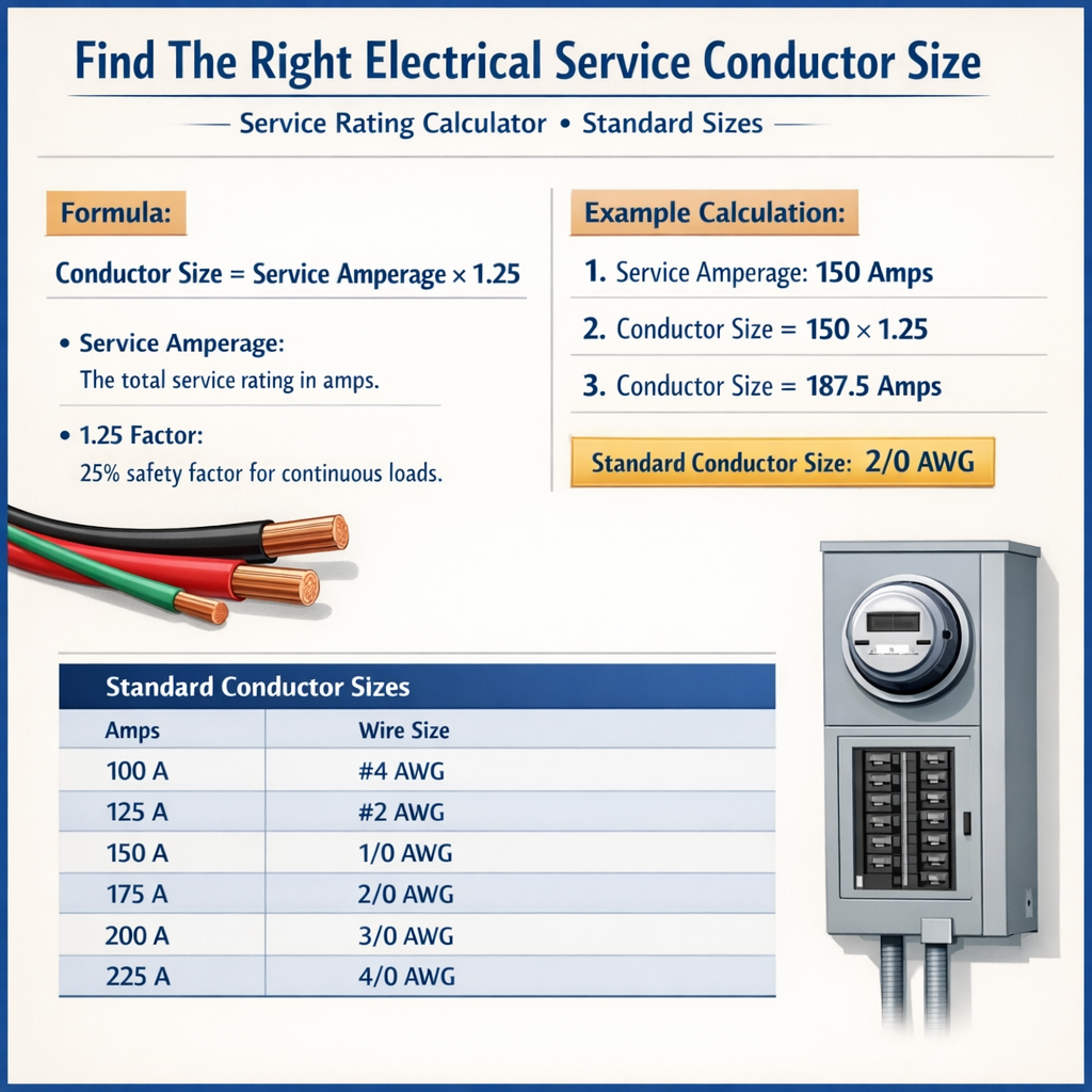
Electrical Service Conductor Size and Service Rating Calculator (Standard Sizes)
Scope and practical objectives
This technical guide explains methods to determine the proper service conductor size, relates service rating selection, and details standard conductor sizes used internationally. It emphasizes calculation steps, derating factors, voltage drop, and normative cross-references so engineers can apply compliant solutions for residential, commercial, and industrial services.Key technical concepts and definitions
Ampacity and continuous load
Ampacity is the maximum current a conductor can carry continuously without exceeding its insulation temperature rating under specified conditions. For regulatory compliance in many jurisdictions the ampacity required for continuous loads is increased by a factor (commonly 125% for NEC-guided systems). This is applied as: I_required = I_load × 1.25 where: - I_required = design ampacity required (A) - I_load = actual continuous load current (A) Typical value: 1.25 (125%) for loads expected to run continuously (>3 hours) per NFPA 70 (NEC).Fundamental electrical formulas
Use these core formulas to compute currents, power, and voltage drop. All formulas are presented using plain text notation.- Single-phase current from real power: I = P / (V × PF) Variables: P = real power (W) V = line-to-neutral or supply voltage (V) for single-phase PF = power factor (unitless, typical 0.8–1.0) Typical example values: P = 4500 W, V = 240 V, PF = 1.0 → I = 18.75 A- Three-phase current (balanced, line-to-line voltage): I = P / (sqrt(3) × V × PF) Variables: P = real power (W) V = line-to-line voltage (V) PF = power factor (0.8–1.0) sqrt(3) ≈ 1.732- Voltage drop (single-phase, round-trip): V_drop = I × R × 2 × L Variables: I = current (A) R = conductor resistance (Ω/m) L = one-way length (m) Round-trip multiplier = 2 for single-phase circuits.- Voltage drop (three-phase, balanced): V_drop_3ph = sqrt(3) × I × (R × cosφ + X × sinφ) × L Simplified (neglecting reactance for resistive circuits): V_drop_3ph ≈ sqrt(3) × I × R × L- Conductor resistance from cross-sectional area: R = ρ × (1 / A) or R = 0.017241 / A Variables: ρ = resistivity factor for copper at 20 °C ≈ 0.017241 Ω·mm²/m A = conductor cross-sectional area (mm²) Typical: for copper A = 5.26 mm² → R ≈ 0.017241 / 5.26 ≈ 0.00328 Ω/m- Sizing by current density (engineering approximation when table lookup unavailable): A_required = I_required / J Variables: A_required = required cross-sectional area (mm²) I_required = design ampacity current (A) J = designing current density (A/mm²) Typical J ranges: - 2.5–6.0 A/mm² depending on installation conditions and insulation type Conservative typical value for insulated multi-core cable in conduit: J ≈ 3 A/mm²Standards, ratings, and referencing normative tables
Design must reference recognized standards for ampacity, conductor mechanical rating, and service equipment. Key authoritative documents: - NFPA 70 (NEC) — United States: https://www.nfpa.org/NEC - IEC 60364 series — International electrical installations: https://www.iec.ch/standards - IEC 60228 — Conductors of insulated cables (cross-sectional area definitions): https://www.iec.ch - IEEE Std. 141 (Red Book) and IEEE Std. 142 for grounding practices (useful guidance): https://www.ieee.org - IET Wiring Regulations (BS 7671) — UK: https://www.theiet.org/codes-guidance/ - EN/IEC guidance for voltage drop recommendations: IEC 60364-5-52Always use the local edition of applicable standards; regional amendments or country-specific code may modify required multipliers, ampacity tables, or service rating rules.Standard conductor sizes and common ampacity references
Below are commonly used conductor cross-sectional sizes (AWG and metric) and typical ampacity ranges. Values are representative; always verify against the specific standard and insulation column used (e.g., 60 °C, 75 °C, 90 °C ratings in NEC 310.15(B)(16) or IEC tables).| Common Size (AWG / mm²) | Approx. mm² | Typical Ampacity Range (Copper, A) | Typical Ampacity Range (Aluminum, A) |
|---|---|---|---|
| 14 AWG | 2.08 | 15–20 | — |
| 12 AWG | 3.31 | 20–25 | — |
| 10 AWG | 5.26 | 30–35 | — |
| 8 AWG | 8.37 | 40–55 | — |
| 6 AWG | 13.30 | 55–75 | — |
| 4 AWG | 21.15 | 70–95 | — |
| 2 AWG | 33.62 | 95–130 | — |
| 1/0 AWG | 53.48 | 125–170 | — |
| 2/0 AWG | 67.43 | 145–195 | — |
| 3/0 AWG | 85.01 | 165–225 | — |
| 4/0 AWG | 107.2 | 195–260 | — |
| 16 mm² | 16.0 | 70–110 | 50–85 |
| 25 mm² | 25.0 | 90–150 | 65–115 |
| 35 mm² | 35.0 | 115–190 | 85–140 |
| 50 mm² | 50.0 | 150–230 | 110–185 |
| 70 mm² | 70.0 | 185–280 | 140–225 |
| 95 mm² | 95.0 | 230–360 | 175–285 |
| 120 mm² | 120.0 | 260–400 | 200–315 |
Service rating selection and conductor interaction
Service rating refers to the ampere capacity of the service disconnect and the associated bus and is typically standardized: 60 A, 100 A, 150 A, 200 A, 400 A, 600 A, etc. The selected service rating sets the minimum conductor ampacity and terminal ratings. Key points:- The service conductors must have ampacity not less than the service rating, after applying required adjustments (NEC 230.6, 310.15). - For parallel conductors in service runs, follow rules for parallel installation (NEC 310.10) and conductor sizes (normally 1/0 AWG and larger for copper to be eligible for paralleling). - Equipment terminals are rated for a specific temperature (e.g., 75 °C or 90 °C). Conductor ampacity must be determined relative to the terminal temperature rating.Derating and ambient temperature corrections
Ampacity tables are given for a reference ambient temperature (commonly 30 °C). Correction factors are applied for different ambient temperatures and for multiple conductors bundled together:- Temperature correction: I_corrected = I_table × F_temp - Multi-conductor adjustment: I_corrected = I_table × F_groupTypical F_temp values (examples; consult relevant table): - At 40 °C: F_temp might be 0.91 for 75 °C column - At 50 °C: F_temp might be 0.82Typical F_group values: - More than three current-carrying conductors in a raceway require derating (e.g., for 4–6 conductors F_group ≈ 0.80, for 7–9 F_group ≈ 0.70 — values vary by code).Always multiply all derating factors to get the final allowable ampacity.Voltage drop guidance and formula usage
Design practice usually limits circuit voltage drop to maintain equipment performance: - Recommended maximum voltage drop for feeders + branch circuits combined: typically 5% (guidance only; some local codes stricter). - Recommended maximum drop for branch circuits alone: 3%.Use the formulas in the previous section to compute V_drop and check percent: Percent_drop = (V_drop / V_supply) × 100%Example of resistance computation: R_per_meter = 0.017241 / A_mm2 Then apply V_drop formulas.Worked example 1 — Residential single-phase branch: 4.5 kW water heater
Problem statement: A 4,500 W electric water heater is supplied from a 240 V single-phase distribution. One-way cable length from panel to heater is 30 m. The heater is considered a continuous load. Determine required conductor size (copper), confirm ampacity, and compute voltage drop. Assume PF = 1. Use J method for preliminary sizing and verify using ampacity selection to nearest standard size.Step 1 — Compute load current: I_load = P / V = 4,500 W / 240 V = 18.75 AStep 2 — Apply continuous load factor (NEC practice): I_required = I_load × 1.25 = 18.75 × 1.25 = 23.4375 AStep 3 — Preliminary cross-sectional area by current density: Assume J = 3 A/mm² (conservative for insulated conductor in conduit). A_required = I_required / J = 23.4375 / 3 ≈ 7.8125 mm²Select the next standard conductor: 10 AWG (≈ 5.26 mm²) is smaller than requirement; 8 AWG (≈ 8.37 mm²) is slightly larger and acceptable. Thus choose 8 AWG copper (≈ 8.37 mm²).Step 4 — Verify ampacity (typical table): Typical ampacity of 8 AWG copper (depending on temperature column) is in the 40–55 A range — well above 23.44 A. Therefore conductor meets ampacity requirements.Step 5 — Voltage drop calculation: Compute conductor resistance per meter using copper resistivity: R = 0.017241 / A = 0.017241 / 8.37 ≈ 0.00206 Ω/mRound-trip length = 2 × 30 m = 60 m V_drop = I_required × R × Round-trip = 23.4375 × 0.00206 × 60 ≈ 2.90 VPercent voltage drop = (2.90 / 240) × 100% ≈ 1.21% (comfortably below 3% branch limit)Result summary: - Selected conductor: 8 AWG copper (≈ 8.37 mm²) - Ampacity margin: ample (typical ampacity 40–55 A) - Voltage drop: ≈ 2.90 V (1.21%) — acceptable.Notes: - If local code prescribes 10 AWG for this load using different J or ampacity assumptions, always defer to local code and manufacturer's terminal temperature rating.Worked example 2 — Three-phase motor load: 50 kW at 400 V
Problem statement: A 50 kW three-phase motor installation at 400 V (line-to-line), PF = 0.90, expected to be a continuous duty for sizing purposes. Cable run length one-way = 50 m. Determine conductor cross-sectional area (copper), check voltage drop, and confirm selection.Step 1 — Compute operating current: I_load = P / (sqrt(3) × V × PF) I_load = 50,000 W / (1.732 × 400 V × 0.90) = 50,000 / 623.52 ≈ 80.16 AStep 2 — Apply continuous load multiplier (if required): I_required = I_load × 1.25 = 80.16 × 1.25 ≈ 100.20 AStep 3 — Preliminary area by current density: Choose J = 3 A/mm² (conservative). A_required = I_required / J ≈ 100.20 / 3 ≈ 33.40 mm²Select nearest standard size: 35 mm² copper (standard metric conductor).Step 4 — Verify ampacity: Typical ampacity of 35 mm² copper widely supports currents well above 100 A (often 115–190 A depending on conditions), so selected 35 mm² is appropriate. For NEC-based projects you might choose nearest AWG equivalents or 2/0–3/0 depending on local conventions.Step 5 — Voltage drop calculation (three-phase): Compute resistance: R = 0.017241 / 35 ≈ 0.0004926 Ω/mV_drop_3ph ≈ sqrt(3) × I_required × R × L V_drop_3ph ≈ 1.732 × 100.20 A × 0.0004926 Ω/m × 50 m Intermediate: 100.20 × 0.0004926 ≈ 0.04938 Times 50 m → 2.469 Times 1.732 → ≈ 4.277 VPercent voltage drop = (4.277 / 400) × 100% ≈ 1.07% (well below typical 3%–5% recommendations)Result summary: - Selected conductor: 35 mm² copper - Ampacity: adequate for 100.2 A design current - Voltage drop: ≈ 4.28 V (1.07%) — acceptable.Notes: - If installation has significant reactance (long runs with inductive loads), include X and use the complete V_drop_3ph formula. - Motor starting currents may require different feeder sizing or protection; this calculation addresses continuous thermal sizing.Parallel conductors and high-current services
When a service rating is high (commonly ≥ 400 A), parallel conductors may be used. Rules include: - Only certain conductor sizes and types are permitted for paralleling (consult code: NEC 310.10(G)). - Ensure identical length, conductor material, and insulation; same size for all paralleled conductors in a phase. - For long runs, paralleled conductors reduce voltage drop and heating; check unbalance and fault currents.Protection coordination and conductor selection
Selecting conductor size must account for overcurrent protection devices (fuses, breakers). Key checks: - Conductor ampacity must be at least the rating of the overcurrent device unless exceptions apply. - Ampacity must be adequate for load × 125% where applicable so the protective device will not cause nuisance trips but also provide safety. - Verify that conductor short-circuit withstand and mechanical capacity are sufficient for fault current at the point of installation.Best practices and step-by-step sizing workflow
Follow a disciplined workflow to size service conductors:1. Define service rating and system parameters: - Supply type (single-phase, three-phase) - Nominal voltages (e.g., 230/400 V, 120/240 V, 480 V) - Ambient temperature and installation method 2. Calculate actual load currents using P, V, PF formulas. 3. Apply continuity and diversity factors per applicable code (continuous loads get 125% multiplier). 4. Apply temperature correction and grouping adjustment factors. 5. Choose conductor size from manufacturer and code tables to meet adjusted ampacity. 6. Check voltage drop using R (derived from conductor area) and length; ensure percent drop within recommended limits. 7. Verify overcurrent protective device compatibility and terminal ratings. 8. Document references, tables used, and assumptions (ambient temp, insulation type, PF, cable type).Practical considerations and installation notes
- Always select conductor insulation class compatible with terminal temperature ratings (e.g., 75 °C or 90 °C). - For aluminum conductors, choose larger cross-sectional area than copper for equivalent ampacity; check terminations for aluminum (oxidation, anti-oxidant). - Consider future capacity and spare conductors in raceways for anticipated load increases. - Protect conductors against mechanical damage and follow correct bending radii for cable installation. - In corrosive or wet environments, use appropriate cable jackets and protection measures.References and further reading
- NFPA 70, National Electrical Code (NEC): https://www.nfpa.org/NEC — primary reference for conductor ampacity and service sizing in the United States. - IEC 60364 series — Electrical installations of buildings: https://www.iec.ch/standards — international guidance for design and safety. - IEC 60228 — Conductors of insulated cables: https://www.iec.ch/standards — definitions of conductor sizes and tolerances. - IET Wiring Regulations (BS 7671): https://www.theiet.org/codes-guidance/ — UK industry guidance on installation rules. - IEEE Guide for Electrical Power Distribution for Industrial Plants (IEEE Std. 141): https://www.ieee.org — engineering practice guides. - Manufacturer cable datasheets and NEMA/EN product standards for detailed ampacity and derating data.Final notes and compliance reminder
This article presents methods, typical values, and worked examples to guide conductor sizing and service rating decisions. Always confirm final conductor size, ampacity, corrections, and protective device sizing against the local code edition, project specifications, and manufacturer data. When in doubt, consult a licensed electrical engineer or the authority having jurisdiction (AHJ) to ensure regulatory compliance.