Accurate full load current calculation ensures motor selection, protection, and efficient electrical system design performance.
This article describes the best full load current calculator tool, formulas, examples, and normative references.Motor Full-Load Current Calculator — Technical Tool
Understanding Full Load Current (FLC) and Its Importance
Full Load Current (FLC) is the electrical current a motor draws when delivering its rated mechanical output under specified conditions. Engineers use FLC to size conductors, protective devices, starters, and motor controllers while verifying thermal and voltage-drop limits in electrical networks.
When FLC matters
- Sizing power cables and busbars to prevent overheating and voltage drop.
- Selecting appropriate circuit breakers, fuses, and overload relays per code requirements.
- Specifying power distribution and switchgear to ensure safe continuous operation.
- Estimating energy consumption and running costs for efficiency optimization.
- Choosing control strategies (DOL, soft-starter, VFD) based on starting currents and torque.
Core Formulae for Motor Full Load Current Calculation
Presenting the fundamental electrical relationships to compute motor full load current for single-phase and three-phase machines.
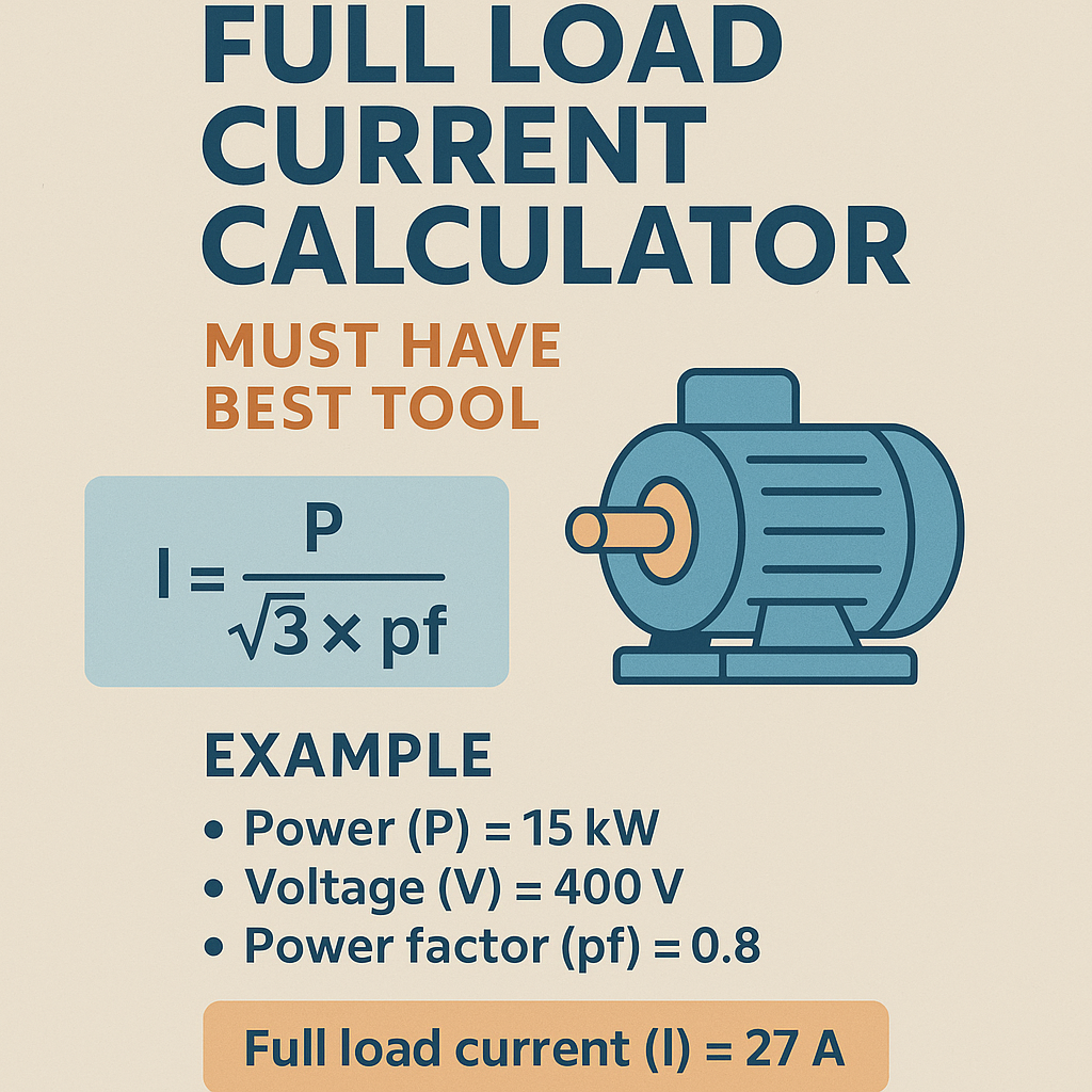
Three-phase motors (line-to-line voltage V):
Single-phase motors (line voltage V):
When motor power is given in horsepower (HP):
Explanation of variables and typical values
- P — Mechanical power output, in kW. Typical units delivered by manufacturers: kW or HP.
- I — Line current in amperes (A), full-load operating current.
- V — Line-to-line voltage for three-phase (e.g., 400 V, 460 V) or line voltage for single-phase (e.g., 230 V).
- PF — Power factor (unitless). Typical synchronous/induction motor PF under load: 0.8–0.95. Use 0.85 as a conservative default for small motors, higher for large motors.
- Eff — Efficiency (η, unitless). Typical IE efficiency classes: IE1–IE4. Typical values: 0.75–0.98 depending on size and class. Use 0.85–0.95 for mid-size motors.
- √3 — Square root of three (≈1.732) used to convert three-phase apparent power (VA) to line current.
Assumptions, Rounding and Typical Error Sources
Any calculator must state assumptions: whether P is shaft output or input, whether PF and efficiency are nameplate versus measured, and ambient/altitude corrections.
- Manufacturer nameplate FLC already accounts for typical efficiency and PF; where available, use it instead of calculated values.
- Rounding: calculate to two decimal places then round up conservatively when sizing conductors or protective devices.
- Starting currents (locked-rotor or inrush) are typically 4–10× FLC depending on motor design and starting method; calculators should provide a range and recommend control strategy.
- Ambient temperature and conductor grouping affect ampacity — apply correction factors per local code.
Extensive Tables of Common Motor Full Load Currents
Tables below present computed FLC values for common motor powers and standard voltages using clearly-stated conservative assumptions: PF = 0.88 and Eff = 0.92 for three-phase motors, PF = 0.85 and Eff = 0.90 for single-phase motors. These values are illustrative—use nameplate or manufacturer data for final design.
| Motor Power (kW) | Motor Power (HP) | Three-phase FLC @ 400 V (A) | Three-phase FLC @ 460 V (A) | Three-phase FLC @ 690 V (A) |
|---|---|---|---|---|
| 0.75 | 1.01 | 1.47 | 1.28 | 0.85 |
| 1.1 | 1.48 | 2.16 | 1.88 | 1.25 |
| 3 | 4.02 | 5.87 | 5.10 | 3.39 |
| 5.5 | 7.38 | 10.78 | 9.37 | 6.23 |
| 7.5 | 10.05 | 14.70 | 12.77 | 8.49 |
| 15 | 20.10 | 29.40 | 25.55 | 17.00 |
| 30 | 40.20 | 58.80 | 51.10 | 34.00 |
| 55 | 73.93 | 107.80 | 93.77 | 62.31 |
| 75 | 100.44 | 147.00 | 127.73 | 84.94 |
| 110 | 147.06 | 215.60 | 187.10 | 124.63 |
Notes: Values computed with I = (kW × 1000) / (√3 × V × PF × Eff). For three-phase, PF = 0.88, Eff = 0.92 assumed.
| Motor Power (HP) | Motor Power (kW) | Single-phase FLC @ 115 V (A) | Single-phase FLC @ 230 V (A) |
|---|---|---|---|
| 1 | 0.746 | 8.08 | 4.04 |
| 3 | 2.238 | 24.24 | 12.12 |
| 5 | 3.730 | 40.43 | 20.21 |
| 7.5 | 5.595 | 60.60 | 30.30 |
| 10 | 7.460 | 80.81 | 40.40 |
| 20 | 14.92 | 161.62 | 80.81 |
Notes: Single-phase values assume PF = 0.85 and Eff = 0.90. Real single-phase motor PF/Eff vary widely; consult nameplate.
Design Considerations for a “Must Have” Full Load Current Calculator Tool
A professional FLC calculator must provide accurate results, address real-world constraints, and be straightforward to use. Below are functional and UX features that define the best tool.
Essential functional features
- Input flexibility: accept kW, HP, nameplate FLA, voltage, phase, PF, and efficiency. Allow switching units (metric/imperial).
- Automatic unit conversion and validation for inputs (e.g., accept comma/decimal separators correctly).
- Choice between using nameplate FLA and calculated FLC with clear precedence rules—if nameplate exists, recommend it.
- Starting current estimates (locked-rotor ratio) and configurable multiplier based on NEMA/IEC motor design categories.
- Protection sizing guidance: suggested breaker/fuse trip settings, overload relay ranges, and conductor ampacity with links to code tables.
- Envelope for environmental derating: ambient temperature, altitude, conduit fill, and grouping corrections.
- Exportable results in PDF and CSV with calculation traceability and references to the formulas used.
- Versioned audit trail and a disclaimer for engineering judgment and local code compliance.
User experience (UX) suggestions
- Present results prominently: FLC, recommended breaker size, recommended cable size, and starting current in a summary box.
- Provide inline help tooltips that explain PF, efficiency, and why nameplate data is preferred.
- Validation errors: flag unrealistic inputs (e.g., PF > 1 or efficiency > 1) and suggest corrections.
- Allow defaults for PF and efficiency with an advanced toggle to change these values if measured or manufacturer-specified values are available.
- Include visual charts for current vs. voltage, and typical inrush multiplicative factors for common starting methods.
Protection and Conductor Sizing: How to Use FLC in Practice
FLC is the starting point. Code rules (NEC/IEC/NEMA) prescribe specific multipliers and adjustments for equipment and wiring selection. Below are practical steps and checks.
- Confirm whether P is shaft rating or input power. If shaft rating, use efficiency to compute electrical input power.
- Compute FLC using formula. If manufacturer gives FLA (full-load amps), use the nameplate value to size protective devices per code.
- Apply conductor ampacity tables and environmental correction factors (temperature, grouping). Then choose the next larger standard conductor size.
- For breaker/fuse sizing, follow local code: e.g., NEC Article 430 provides limits for motors, often allowing OCPDs at 250–400% of FLC for short-circuit protection depending on device and motor type. Always verify the specific article and exceptions.
- Select overload relays for continuous protection: typically set to 115%–125% of FLC; check motor service factor and manufacturer recommendations.
Real-World Example 1 — Three-Phase 50 kW Motor at 400 V
Situation: Specify FLC and select conductor and protective device for a 50 kW, 3-phase induction motor. Manufacturer gives no FLA; use conservative PF and efficiency assumptions.
Given
- P = 50 kW (shaft output)
- V = 400 V (line-to-line, three-phase)
- PF assumed = 0.90 (typical for larger motors)
- Eff assumed = 0.95 (IE2–IE3 class)
Calculations
Step 1 — Convert mechanical power to electrical input basis:
Step 2 — Apply three-phase current formula:
Selection guidance
- Rounded FLC ≈ 84.4 A. For conductor sizing, select a cable with ampacity ≥ 84.4 A after applying correction factors.
- Assuming one cable in free air, 80°C copper conductor ampacity tables might indicate 3 × 35 mm² copper (~125 A) or 3 × 25 mm² (~101 A) depending on insulation; choose 25 mm² minimum in many regions but verify local ampacity tables and derating.
- Overload relay: set nominally to motor FLC; typical electromechanical thermal relays set to between 100% and service-factor compensated value. Set relay to 84.4 A (or a range that includes the value) recognizing manufacturer tolerance.
- Short-circuit/overcurrent protection: per NEC Article 430, the branch-circuit short-circuit protective device for motors may be sized up to 250%–400% of motor FLA depending on device. If using a molded-case circuit breaker with an instantaneous trip, consult NEC 430 and local amendments for exact multipliers.
Starting current estimate
If motor locked-rotor current is estimated at 6 × FLC (typical design B induction), starting current ≈ 6 × 84.4 = 506.4 A. If network constraints exist, specify a soft starter or VFD to reduce starting current.
Real-World Example 2 — Single-phase 7.5 HP Motor at 230 V
Situation: Industrial process uses a 7.5 HP single-phase motor, nameplate missing. Engineer must size cable and overload relay.
Given
- HP = 7.5
- V = 230 V (single-phase)
- PF assumed = 0.85 (single-phase motors often have lower PF)
- Eff assumed = 0.90
Calculations
Step 2 — Use single-phase formula:
Selection guidance
- Rounded FLC ≈ 31.8 A. Choose conductor ampacity ≥ 31.8 A after correction factors; likely a 6 mm² copper conductor (approx. 37–40 A depending on insulation and tables) or 8 AWG in imperial units, but verify local ampacity tables.
- Overload protection: set thermal overload relay to include motor service factor. If service factor = 1.15, adjust setting accordingly or follow manufacturer data.
- Starting current: single-phase motors may have higher inrush; estimate locked-rotor factor 6–8 × FLC → 190–255 A. If supply and coordination require, consider soft-start or a dedicated contactor with appropriate inrush rating.
Advanced Topics: Service Factor, Ambient Corrections, and Altitude
Real installations rarely match laboratory conditions. A professional calculator must allow modifiers for service factor (SF), ambient temperature, and altitude derating.
- Service Factor (SF): If motor SF > 1.0, it can deliver more load for short durations. For continuous calculations, do not increase conductor/breaker ratings solely based on SF without checking manufacturer guidance and code limits.
- Ambient temperature correction: Ampacity tables are usually for 30°C. For higher ambient temperatures, apply correction factors per the applicable electrical code or conductor manufacturer.
- Altitude: Reduced cooling at high altitudes reduces allowable current. Apply altitude correction per standards or manufacturer data.
Starting Methods and Their Impact on Electrical Sizing
Starting method directly influences starting current and mechanical stress. The calculator should estimate starting current and advise on appropriate control solutions.
- Direct-On-Line (DOL): Highest inrush (approx. 4–8× FLC). Simple, low-cost, but may stress supply.
- Star-Delta: Reduces starting voltage and current (approximately 1/3 line current during start), but torque reduction and mechanical complexity must be considered.
- Soft Starter: Provides ramped voltage, reduces starting current and mechanical shock; configurable across a wide range.
- Variable Frequency Drive (VFD): Best control over starting torque and current; allows ramp control, energy efficiency, and precise speed regulation.
Calibration, Validation and Traceability
For engineering-grade calculators, include a calibration and validation plan.
- Cross-validate calculator outputs with manufacturer nameplate FLA and independent measurements when available.
- Keep a calculation log exported with input assumptions, date, user, and software version for audits.
- Apply sensitivity analysis: show how PF or efficiency variation impacts FLC and recommended sizes.
Regulatory References and Authoritative External Links
Design must comply with recognized standards. Below are authoritative documents and resources commonly referenced by engineers.
- NEMA MG1 — Motors and Generators: https://www.nema.org/standards (contains motor ratings and performance data)
- IEC 60034 — Rotating Electrical Machines: https://www.iec.ch (international motor standards for testing and ratings)
- NFPA 70 (NEC) — National Electrical Code: https://www.nfpa.org/NEC (U.S. code containing motor circuit requirements, Articles 430)
- IEEE Power and Energy Resources: https://standards.ieee.org (reference for power system studies and motor starting effects)
- European Committee for Electrotechnical Standardization (CENELEC): https://www.cenelec.eu (regional harmonized standards)
Always reference the latest published edition of standards and local amendments when applying code-based multipliers.
Implementation Checklist for an Accurate Online or Embedded Calculator
When building or validating a motor FLC calculator, follow the checklist below to ensure reliability and regulatory compliance.
- Input validation and units management (kW/HP, V, phase).
- Ability to input manufacturer nameplate FLA and override calculated values with audit trail.
- Optional PF and efficiency presets or custom input with recommended defaults by motor size.
- Starting current estimator and recommended starting method based on application.
- Conductor ampacity and breaker/fuse recommendations with links to applicable code sections.
- Ambient and altitude correction factors with mention of applicable standards.
- Exportable and printable calculation report showing formulas, step-by-step values, and references.
- Disclaimer emphasizing the engineer’s responsibility to verify results against local codes and nameplate data.
SEO and Content Strategy for a “Best Tool” Landing Page
If the calculator will be published online, combine technical accuracy with content optimized for discoverability.
- Target keywords: “Motor full load current calculator”, “full load amps calculator”, “FLC calculator”, “motor current sizing tool”.
- Include structured data and plain-text export for crawlers; ensure pages are indexable and accessible without JavaScript-heavy rendering for core content.
- Provide detailed explanation pages (like this) linking from the calculator page to improve topical authority.
- Offer downloadable resources (PDFs with calculation steps, tables, and code references) to increase backlinks and trust signals.
Common Pitfalls and How the Best Calculator Avoids Them
- Pitfall: Using output mechanical power without adjusting for efficiency. Fix: clearly distinguish P_shaft vs P_electrical and provide conversion calculators.
- Pitfall: Ignoring nameplate FLA. Fix: accept and prioritize nameplate FLA with an explicit override for computed values.
- Pitfall: Not accounting for starting inrush. Fix: estimate locked-rotor currents and recommend starting solutions.
- Pitfall: Omitting code-based sizing rules. Fix: include guidance and references to standards (NEC, IEC, NEMA) for final sizing.
Summary of Best Practices for Engineers
- Use manufacturer nameplate FLA when available; otherwise compute FLC with transparent PF/efficiency assumptions.
- Round conservatively for protective devices and conductor selection, applying code-prescribed multipliers.
- Estimate starting current and specify starting method that protects both electrical network and mechanical load.
- Document assumptions, maintain traceability, and validate results with measurements where possible.
- Stay current with normative documents (NEMA, IEC, NFPA/NEC) and local regulations.
Further Reading and Tools
- NEMA MG1 – Motors and Generators: provides performance and testing standards for industrial motors — https://www.nema.org
- IEC 60034 series — rotating electrical machines standards — https://www.iec.ch
- NFPA 70 (NEC) — particularly Article 430 for motors — https://www.nfpa.org/NEC
- IEEE guides on motor starting and system impact studies — https://standards.ieee.org
- Manufacturer technical bulletins and nameplate interpretation guides (Siemens, ABB, WEG) — check vendor technical pages for motor catalogs and FLA tables.
When you design a motor full load current calculator or use one, prioritize transparency, traceability, and code compliance. The tool should always guide engineers to confirm results with manufacturer data and local standards.