This expert-level article details turning radius definitions, measurement methods, geometric formulas, design values, and regulatory requirements.
It includes swept-path methods, overhang considerations, and two comprehensive real-world examples with step-by-step calculations.
Vehicle Turning Radius Calculator
Estimate wheel-path and body turning diameters from wheelbase, equivalent steering angle, and overhangs.
Formulas used
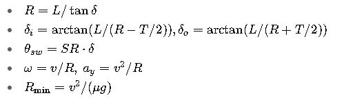
Bicycle model: R = L / tan(δ) (rear axle path).
Inner/outer rear wheel: Rinner = R − T/2, Router = R + T/2.
Outer front body corner: Rofc = √((R + W/2)² + (L + FO)²).
Outer rear body corner: Rorc = √((R + W/2)² + RO²).
Outer front wheel center: Rwheel = √((R + T/2)² + L²).
Approximate wheel-path diameter: Dwheel = 2·Rwheel.
Inner rear corner path radius: Rirc = √((R − W/2)² + RO²).
Body diameter with radial margin c: Dbody = 2·(max(Rofc, Rorc) + c).
Inner/outer rear wheel: Rinner = R − T/2, Router = R + T/2.
Outer front body corner: Rofc = √((R + W/2)² + (L + FO)²).
Outer rear body corner: Rorc = √((R + W/2)² + RO²).
Outer front wheel center: Rwheel = √((R + T/2)² + L²).
Approximate wheel-path diameter: Dwheel = 2·Rwheel.
Inner rear corner path radius: Rirc = √((R − W/2)² + RO²).
Body diameter with radial margin c: Dbody = 2·(max(Rofc, Rorc) + c).
This is a low-speed, steady-turn bicycle model with a rectangular body, equal front/rear tracks and no tire width or mirror allowance. The inner rear corner radius is a point path, not the minimum clearance of the whole vehicle. It does not model steering transitions, trailer articulation or measured manufacturer turning circles.
Curb-to-curb vs wall-to-wall
Curb-to-curb describes the outer wheel sweep; wall-to-wall includes the body sweep. This calculator estimates the outer front wheel-center diameter without tire width. It separately reports the rectangular body envelope plus your radial clearance margin; that margin increases the diameter by twice its value.
Why overhangs matter
A longer front overhang increases the outer front body-corner radius. A longer rear overhang increases both rear corner path radii and can determine the outer body envelope. Overhangs do not change wheel paths when wheelbase, track and steering angle stay fixed.
Which steering angle should I use?
Use the equivalent single-track front steering angle for the bicycle model, not steering-wheel rotation or either individual Ackermann wheel angle. Use measured vehicle geometry; the presets are illustrative.
Quick reference: definitions and measurement conventions
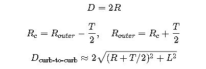
- Turning radius (R) — the radius of the smallest circle the vehicle can negotiate at full steering lock. Some manufacturers and standards use radius, many publish turning circle or turning diameter (diameter = 2·R). The nomenclature is inconsistent in practice; always check whether the number is radius (m) or diameter (m).
- Curb-to-curb (kerb-to-kerb) — measurement that describes the distance needed for the wheels to make a U-turn (usually measured to the outermost wheel track). Wall-to-wall measures the full body sweep (including bumper overhangs) and is larger. Always state which method is used.
- Instantaneous center of rotation (ICR) — the kinematic point about which the vehicle is turning at any instant; used in geometric calculations and in the bicycle/kinematic model.
1) Extensive tables — common, authoritative turning-radius values (many vehicle classes & examples)
Table A — Representative passenger vehicles & small commercial vehicles (manufacturer / measured values)
| Vehicle (example) | Turning value | Type (R / diameter) | Measurement method |
|---|---|---|---|
| Smart ForTwo (2016) | 6.95 m | diameter | curb-to-curb (manufacturer quoted: 22.8 ft turning circle) |
| Toyota Corolla (modern, typical configuration) | 5.2 m | radius (min turning radius — tyre) | manufacturer ‘min. turning radius – tyre’ |
| Toyota Camry (typical reported figure) | 10.9 m | diameter | curb-to-curb |
| Typical small passenger car (compact hatchback) | ≈5.0–6.0 m | radius | curb-to-curb (typical range) |
| Midsize sedan / small SUV | ≈5.5–6.5 m | radius | curb-to-curb (typical) |
Table B — Trucks, vans, buses, design vehicles (engineering / roadway design reference ranges)
| Vehicle / design vehicle | Typical turning radius (radius) | Typical turning diameter | Notes / design context |
|---|---|---|---|
| Delivery van / medium van (e.g., Ford Transit class) | ~6.0–7.5 m | 12–15 m | curb-to-curb typical for urban delivery vehicles |
| Pickup / light-truck (full-size) | ~6.0–8.0 m | — | depends strongly on wheelbase |
| 7.5-ton / medium truck | ~6.5–12 m | — | varies with wheelbase and axle set |
| City transit bus (rigid) | ~8.5–12 m | — | typical curb radii for city buses |
| Tractor-trailer (WB-50 / WB-62 / WB-67 type) | ~9–15 m (centerline) | turning diameter commonly >18 m | used for roadway/intersection design |
Table C — Tight/maneuverable industrial vehicles and specialized equipment
| Vehicle type | Typical outer turning radius (m) | Comment / where to use |
|---|---|---|
| 3-wheel electric forklift | ~1.3–2.0 m | very tight turning; used inside narrow aisles |
| Warehouse reach truck / narrow-aisle | ~1.0–2.5 m (effective) | specialized; depends on load length and stacking geometry |
| Large articulated bus | >7.5–12 m | measured to outer wheel path; swept path methods used for design |
2) All required formulas — geometric (kinematic), steering geometry, dynamics, swept-path
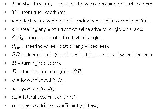
Notation / variables (used throughout)
2.1 Kinematic bicycle model

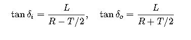
2.2 Ackermann geometry
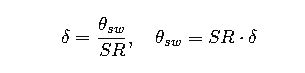
2.3 Steering ratio
2.4 Turning circle conversions
2.5 Dynamic limit
2.6 Swept-path geometry

3) Step-by-step engineering procedure
- Gather all geometric inputs.
- Decide on the reference radius (outer wheel, centerline, body).
- Compute wheel angles using Ackermann.
- Convert to steering wheel travel using SR.
- Run swept-path for body corners.
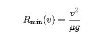
- Perform dynamic feasibility check with ay.
4) Worked real-world examples
Example 1 — Toyota Corolla
- Wheelbase: 2.640 m
- Min turning radius (tyre): 5.2 m
- SR = 13.5:1
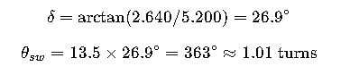
Result: steering wheel requires ~1 turn, turning diameter ~10.4 m.
Example 2 — Toyota Hilux
- Wheelbase: 3.085 m
- Min turning radius (tyre): 6.4 m
- Track: 1.5 m

Result: inner wheel steers ~32°, outer ~26°.
5) Advanced topics
- Vehicles with similar wheelbases may differ due to steering geometry, track width, and overhangs.
- Designers can reduce turning radius by shortening wheelbase, increasing maximum steering angle, or adding four-wheel steering.
- Infrastructure design uses turning-radius standards such as AASHTO design vehicles (WB-50, WB-62, etc.).
6) Engineering checklist
- Gather L,T,δmax,SR
- Convert published radius to chosen reference.
- Compute inner/outer wheel angles.
- Compute steering wheel rotation.
- Run swept-path simulation.
- Check dynamic feasibility.
7) Key formula summary