Comprehensive technical guide for engineers on retaining wall calculations, covering formulas, tables, and variables, explanations. Includes sliding, overturning, bearing-capacity checks, Mononobe-Okabe seismic method, and two detailed worked examples with solutions.
Retaining Wall Quick-Check Calculator
Estimate active earth pressure, overturning & sliding safety factors, and simple bearing check. Use units: meters (m), kN/m³, kN/m².
What assumptions does this calculator use?
• Rankine active earth pressure (no wall friction), simplified triangular pressure plus uniform surcharge term.
• Simple rectangular cross-section: wall stem (constant thickness) + rectangular base slab.
• Unit length = 1 m (per meter run). Concrete weight and soil units in kN/m³ and kN/m².
• This is a quick-check only — hire a licensed engineer for final design.
• Simple rectangular cross-section: wall stem (constant thickness) + rectangular base slab.
• Unit length = 1 m (per meter run). Concrete weight and soil units in kN/m³ and kN/m².
• This is a quick-check only — hire a licensed engineer for final design.
Formulas used (brief)
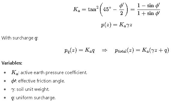
Active coefficient (Rankine, level backfill): Ka = tan²(45° – φ/2).
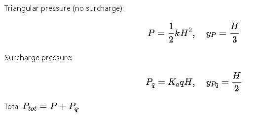
Triangular earth thrust: P_tri = 0.5·γ·H²·Ka.
Surcharge thrust: P_q = q·H·Ka.
Total lateral force: P = P_tri + P_q (kN per meter).
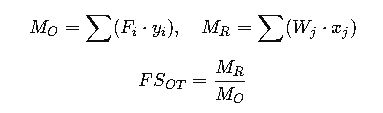
Overturning moment about toe: M_o = P_tri·(H/3) + P_q·(H/2).
Weight (per meter): W = γc·(t_s·H + B·t_b) (kN/m). Resisting moment approx: M_r = W·(B/2).
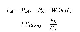
FS_overturning = M_r / M_o. FS_sliding = (W·μ) / P. Bearing pressure check uses resultant eccentricity and rectangular footing formula.
Triangular earth thrust: P_tri = 0.5·γ·H²·Ka.
Surcharge thrust: P_q = q·H·Ka.
Total lateral force: P = P_tri + P_q (kN per meter).
Overturning moment about toe: M_o = P_tri·(H/3) + P_q·(H/2).
Weight (per meter): W = γc·(t_s·H + B·t_b) (kN/m). Resisting moment approx: M_r = W·(B/2).
FS_overturning = M_r / M_o. FS_sliding = (W·μ) / P. Bearing pressure check uses resultant eccentricity and rectangular footing formula.
Why use μ = tan(2φ/3) if blank?
Common engineering approximation for base interface friction angle δ ≈ 2/3·φ (then μ = tan δ).
Limitations
No cohesion, groundwater, seismic or passive pressure considered. Not for piled or anchored walls. Use as preliminary sizing only.
1. Extensive tables of common values (engineer’s quick tables)
These tables are per-meter length (1 m) unless stated otherwise. Values are typical ranges used in preliminary design; site investigation (laboratory tests / CPT / SPT) must be used for final design.
Table A — Typical unit weights, friction angles and cohesion (common soils)
| Soil type | Typical unit weight γ (kN/m³) | Typical unit weight (lb/ft³) | Typical φ′ (deg) | Typical cohesion c′ (kPa) |
|---|---|---|---|---|
| Clean dry sand / gravel | 18 – 20 | 115 – 125 | 30 – 40 | ~0 (drained) |
| Loose sand | 16 – 18 | 100 – 115 | 25 – 30 | ~0 |
| Dense sand | 18 – 20 | 115 – 125 | 35 – 45 | ~0 |
| Silty sand / silt (partly cohesive) | 17 – 19 | 105 – 120 | 20 – 30 | 0 – 10 |
| Clay (normally consolidated) | 17 – 19 | 105 – 120 | 10 – 25 | 10 – 50 |
| Firm clay (stiffer) | 18 – 20 | 115 – 125 | 15 – 30 | 20 – 150 |
| Gravelly fill | 19 – 21 | 120 – 130 | 30 – 40 | ~0 – small |
| Rock (intact) | 25 – 27 | 160 – 170 | n/a | very large |
Table B — Rankine earth-pressure coefficients (Ka, Kp) for common φ (degrees)
| φ (deg) | Ka (active) | Kp (passive) |
|---|---|---|
| 0 | 1.0000 | 1.0000 |
| 5 | 0.8397 | 1.1910 |
| 10 | 0.7041 | 1.4203 |
| 15 | 0.5888 | 1.6984 |
| 20 | 0.4903 | 2.0396 |
| 25 | 0.4059 | 2.4639 |
| 30 | 0.3333 | 3.0000 |
| 35 | 0.2710 | 3.6902 |
| 40 | 0.2174 | 4.5989 |
| 45 | 0.1716 | 5.8284 |
Table C — Typical design safety factors (common practice)
| Limit state | Typical recommended minimum factor |
|---|---|
| Sliding (static) | FS ≥ 1.50 |
| Overturning (moment) | FS ≥ 1.50 – 2.00 |
| Bearing capacity | FS ≈ 2.5 – 3.0 |
| Seismic pseudo-static cases | FS ≥ 1.1 (sliding under earthquake) |
2. Complete list of formulas for retaining-wall calculations and variable definitions
2.1 Lateral earth pressure (Rankine — cohesionless, horizontal backfill)
2.2 Coulomb earth pressure (includes wall friction δ and backfill slope β)
General form considers:
- ϕ= soil friction angle
- δ= wall-soil friction angle (0 ≤ δ ≤ φ)
- β= backfill surface slope
- θ= wall face inclination
Practical δ: between 1/3 φ and 2/3 φ.
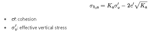
2.3 Cohesive soils (Rankine extension)
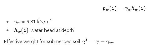
2.4 Hydrostatic (pore-water) pressure
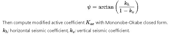
2.5 Seismic earth pressure — Mononobe-Okabe (pseudo-static)
2.6 Resultant force and line of action
2.7 Sliding check
2.8 Overturning check
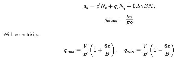
2.9 Bearing capacity (Terzaghi simplified)
3. Two detailed real-world worked examples
Example 1 — Small garden gravity wall
- H = 1.5 m
- φ′ = 30°, Ka = 0.3333
- γ = 18 kN/m³
- Concrete γc = 24 kN/m³
- Wall thickness = 0.5 m, W = 18.0 kN/m
- δ = 20°
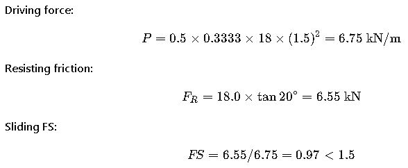
Result: Not safe. Increase base width, add key, or change wall type.
Result: Fails all checks → requires wider base, thicker sections, or alternative design.
4. Practical design notes
- Always begin with site investigation: φ′, c′, γ, groundwater.
- Drainage is critical: design for full water pressure unless proven otherwise.
- Interface friction δ: assume 1/3 φ to 2/3 φ depending on roughness.
- Passive resistance is unreliable; use only if proven.
- Seismic design: use Mononobe-Okabe or advanced analysis.
- Bearing capacity: check eccentricity and ensure qmax ≤ qallow.
- Surcharges: always include traffic, compaction, or storage loads.
- Run sensitivity checks varying φ, water depth, load assumptions.
5. Checklist for calculation workflow
- Collect soil parameters.
- Select wall type.
- Compute earth pressures.
- Add surcharge, water, seismic.
- Compute resultant forces.
- Compute wall weight and centroid.
- Check sliding FS ≥ 1.5.
- Check overturning FS ≥ 1.5–2.0.
- Check bearing capacity FS ≥ 2.5–3.0.
- Iterate geometry or reinforce as required.
6. Engineering tips
- Preliminary base width for cantilever walls: about 0.5–0.6H.
- Use Coulomb if wall friction or sloping backfill exists.
- Model worst-case groundwater if uncertain.
- Tall or critical walls: use advanced numerical modeling.