This technical guide explains converting active power (watts) to apparent power (volt-amperes) precisely and reliably.
🔄 ¿Necesitas la conversión inversa? Si tu cálculo va de VA a WATTS (el sentido contrario de esta página), usa nuestra calculadora de VA a WATTS con tabla completa, ejemplos resueltos y fórmulas detalladas.
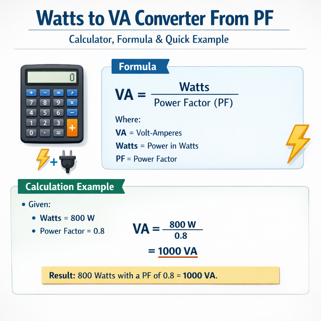
Includes formulas, variable explanations, tables, step-by-step calculations, and compliance references for engineering applications worldwide use.Watts to volt-ampere (VA) converter using power factor
Fundamental concepts: watts, volt-amperes, and power factor
Understanding the conversion from watts (W) to volt-amperes (VA) requires clarity about three electrical quantities:
- Active power (P), measured in watts (W): energy converted to useful work or heat per unit time.
- Apparent power (S), measured in volt-amperes (VA): product of RMS voltage and RMS current, representing the total power flow in the circuit.
- Power factor (PF): dimensionless ratio between active power and apparent power, PF = P / S, typically 0 < PF ≤ 1 for lagging loads.
Engineers convert W to VA primarily to size transformers, conductors, protection devices, and generators, since those devices respond to apparent power.
Core conversion formulas and variable definitions
Single-phase and three-phase systems use the same underlying relationship between active and apparent power, with additional factors for three-phase geometry. Present the formulas using only HTML constructs for clarity.
Basic relationship (universal)
- P = Active power in watts (W).
- S = Apparent power in volt-amperes (VA).
- PF = Power factor (unitless, typically between 0.5 and 1 for most equipment).
- Typical PF values: resistive heater ≈ 1.0, incandescent lamp ≈ 0.95–1.0, induction motor ≈ 0.7–0.9, switch-mode power supply ≈ 0.6–0.99 (with PFC).
Single-phase systems
For single-phase circuits the current calculation ties to apparent power directly:
Therefore, to find current given watts and PF:
- I_rms = RMS current in amperes (A).
- V_rms = System RMS voltage in volts (V), typical values: 120 V, 230 V, 240 V.
Three-phase systems (balanced)
For balanced three-phase circuits the line quantities relate to apparent power:
Given active power P_total, apparent power is:
To find line current:
- V_line = Line-to-line RMS voltage (V), typical industrial values: 400 V, 480 V, 600 V.
- sqrt(3) ≈ 1.73205 (mathematical constant inherent to three-phase geometry).
Reactive power relations (to size reactive compensation)
Reactive power Q (var) relates to P and S as follows:
- Q = Reactive power in volt-amperes reactive (VAR).
- tan(arccos(PF)) computes the reactive-to-active ratio from PF.
Detailed variable explanation and typical ranges
- P (W): measured by true-power meters, wattmeters, or energy meters. Typical residential single-loads: lights 5–100 W, refrigerator 100–800 W.
- PF (unitless): depends on load type: resistive ≈ 0.95–1.0; small induction motors ≈ 0.6–0.85 unloaded; large motors ≈ 0.85–0.95 at rated load; power supplies with active PFC ≈ 0.95–0.99.
- V_rms (V): select nominal voltage per region and equipment. Use actual measured RMS when precision is required.
- S (VA): used to rate transformers, UPS, and circuit components; devices are typically specified by VA or kVA.
Extensive typical-values tables
| Appliance / Load | Typical Active Power P (W) | Typical Power Factor PF | Apparent Power S at 230 V (VA) | Line Current at 230 V (A) |
|---|---|---|---|---|
| LED Lighting (10 bulbs) | 100 | 0.9 | 111 | 0.48 |
| Desktop Computer + Monitor | 300 | 0.95 | 316 | 1.38 |
| Air Conditioner (small, inverter) | 1,200 | 0.95 | 1,263 | 5.50 |
| Washing Machine (motor + electronics) | 800 | 0.8 | 1,000 | 4.35 |
| Induction Motor (1.5 kW rated) | 1,500 | 0.85 | 1,765 | 7.68 |
| Microwave Oven | 1,200 | 0.95 | 1,263 | 5.50 |
| Resistive Heater | 2,000 | 1.0 | 2,000 | 8.70 |
Notes: Apparent power S = P / PF. Line current = S / V_rms. Values rounded for clarity.
| Three-phase Load | P_total (kW) | PF | S_total (kVA) | Line Current at 400 V (A) |
|---|---|---|---|---|
| Small Workshop (motors, lights) | 10 | 0.85 | 11.76 | 17.00 |
| Medium Machine (single large motor) | 30 | 0.9 | 33.33 | 48.08 |
| Industrial Plant Section | 150 | 0.95 | 157.89 | 227.35 |
| Data Center Rack Bank | 50 | 0.99 | 50.51 | 72.92 |
Step-by-step procedures for conversion and sizing
Procedure for single-phase load: convert W to VA and compute current
- Measure or obtain active power P (W) and nominal RMS voltage V_rms (V).
- Determine PF (use measured PF from a power analyzer or apply typical PF for the load).
- Compute apparent power: S = P / PF.
- Compute RMS current: I_rms = S / V_rms.
- Use S (VA) to size UPS/transformer/circuit breaker and I_rms for conductor sizing and protection coordination.
Procedure for three-phase load: convert W to VA and compute line current
- Obtain P_total (W), PF, and line voltage V_line (V).
- Compute S_total = P_total / PF.
- Compute line current: I_line = S_total / (sqrt(3) × V_line).
- Verify equipment ratings: use S_total (kVA) for transformer or generator kVA rating; use I_line for conductor and protection sizing.
Examples with complete development and detailed solutions
Example 1: Single-phase residential inverter load
Problem statement: A solar inverter supplies a household load with measured active power P = 3,200 W at an average PF = 0.92. The nominal output is 230 V RMS single-phase. Determine the apparent power S in VA, the RMS current I_rms, and the reactive power Q.
Step 1 — Compute apparent power:
Step 2 — Compute RMS current at 230 V:
Interpretation: The inverter must be sized at least 3.48 kVA. Cable and breaker selection should accommodate 15.12 A continuous plus appropriate derating. If PF correction to 0.99 is required, compute required capacitor reactive power:
Capacitor needed (VAR to add, reducing inductive Q): Q_capacitor = Q_initial - Q_target = 1,363.8 - 452.8 = 911.0 VAR
Therefore, install approximately a 0.91 kVAR capacitor bank to reach PF ≈ 0.99 (subject to dynamic conditions and transient behavior).
Example 2: Three-phase industrial motor bank and PF correction
Problem statement: An industrial machine room has three identical motors delivering total active power P_total = 75 kW. The measured average PF = 0.86. The plant nominal line voltage is 400 V three-phase. Determine S_total (kVA), line current I_line, reactive power Q, and the capacitor bank size to correct PF to 0.95.
Step 1 — Compute total apparent power:
Step 2 — Compute line current for balanced three-phase system:
Step 3 — Compute reactive power Q_initial:
Compute arccos(0.95) ≈ 0.31756 rad; tan(0.31756) ≈ 0.3270
Step 5 — Capacitor reactive power required:
Summary: Size transformer or generator at least 87.21 kVA; per-phase current ≈ 125.9 A; install ~20 kVAR of power factor correction capacitors to increase PF to ~0.95. Re-evaluate under dynamic loading and coordinate controllers to avoid overcompensation leading to leading PF during low loads.
Example 3: Sizing a UPS system for critical loads (additional practical case)
Problem statement: A server rack consumes P = 12 kW with PF measured at 0.97. The facility uses a single-phase output UPS at 230 V. Determine the required UPS VA rating and the UPS output current.
Recommendation: Select a UPS rated at least 13 kVA to maintain margin for harmonics, inrush currents, and future expansion. Ensure UPS output breakers and wiring rated above 60 A to permit safe continuous operation following relevant electrical codes.
Practical engineering considerations and pitfalls
- Always use measured PF when available; assumed PFs can cause undersized equipment and thermal issues.
- Account for harmonics: non-sinusoidal currents increase RMS heating effects; specify UPS and transformers for kVA and harmonic content (THD).
- Continuous loads: size equipment with 125% or code-required derating for continuous duty as specified by local codes (NEC, IEC).
- Transient inrush: motors and supplies create start-up currents exceeding steady-state values—coordinate protective devices and consider thermal-magnetic behavior.
- PF correction: perform staged correction to avoid overcompensation and resonance with supply network; use switched capacitor banks or active filters for dynamic loads.
Standards, normative references, and authoritative resources
Relevant international standards and authority documents engineers should consult:
- IEC 60038 — Standard voltages (for nominal voltage references): https://webstore.iec.ch/publication/4544
- IEC 61000 series — Electromagnetic compatibility and harmonic performance guidance: https://www.iec.ch/standards
- IEEE Std 141 (Green Book) — Power distribution for industrial plants (engineering guidance): https://standards.ieee.org/standard/141-1993.html
- IEEE Std 519 — Recommended practices and requirements for harmonic control in electric power systems: https://standards.ieee.org/standard/519-2014.html
- NIST Handbook 44 and NIST resources for measurement accuracy of power meters: https://www.nist.gov/
- Local electrical codes (example: NFPA 70 / NEC in the United States) for conductor and device sizing: https://www.nfpa.org/
These references inform safe and compliant design choices for converting watts to VA and for selecting associated equipment.
Best practices for implementation in design documents
- Document measured PF and voltage under representative load conditions; do not rely solely on nameplate values.
- Specify equipment by apparent power (VA or kVA) with margins: typical margin 10–25% depending on uncertainty and transient conditions.
- Include harmonic distortion and crest factor requirements in specifications for UPS and transformers when loads include non-linear devices.
- Design PF correction at the appropriate level (point-of-common-coupling, distribution feeder, load bank) and include control strategy to avoid overcorrection.
- Perform a short-circuit and coordination study if the load or changes affect protection settings or fault currents.
Common questions and quick answers
- Q: Can PF be greater than 1? A: No. PF is the ratio P/S and cannot exceed 1 for linear passive systems.
- Q: Is apparent power always larger than active power? A: Yes, S ≥ P; equality only at PF = 1.
- Q: When sizing a transformer or UPS, should I use P or S? A: Use S (VA/kVA) because those devices respond to apparent power.
- Q: Does harmonic distortion affect VA calculations? A: Yes. Harmonics increase RMS currents and can increase apparent power beyond ideal sinusoidal calculations; adjust for THD and use true RMS measurements.
Checklist for engineers converting W to VA in real projects
- Collect accurate P, measured PF, and actual operating V_rms for each load.
- Compute S = P / PF for each load and sum VA carefully (for non-coincident loads consider diversity and load factors).
- For three-phase loads, convert per formula including sqrt(3) for line current sizing.
- Include margins for transients, harmonics, continuous duty derating, and maintenance contingencies.
- Cross-check with equipment manufacturer recommendations and applicable standards (IEC, IEEE, local codes).
Further technical reading and authoritative links
- IEEE Xplore digital library — search for "power factor correction", "transformer sizing", and "harmonics": https://ieeexplore.ieee.org/
- IEC Webstore — normative documents on voltage and EMC: https://webstore.iec.ch/
- NEMA — motor power factor guidance and data sheets: https://www.nema.org/
- NIST — measurement standards and instrumentation guidance: https://www.nist.gov/
Final technical remarks
Converting watts to VA is a fundamental calculation in electrical engineering with direct implications for equipment selection, safety, and compliance. Engineers must combine accurate measurements, appropriate formulas, and relevant standards to produce reliable designs. When in doubt, perform on-site power analysis with a three-phase power analyzer, include harmonic analysis, and consult device manufacturers and standards listed above for certification and rating details.