This calculator guides precise sizing of solar panels to match consumption and maximize savings efficiently.
Step-by-step methodology integrates irradiance, losses, panel ratings, and economics for optimized system design performance analysis.
Operational principles of a solar panel quantity calculator
A robust calculator converts a customer’s energy profile into a photovoltaic (PV) array size by combining measured consumption, local solar resource data, component ratings, and system-level loss factors. It must model daily energy requirements, peak sun hours, panel power ratings, inverter behavior, temperature derating, shading, orientation, and safety margins to produce a technically valid recommendation.Key computational stages:- Establish target energy output (E_target) in kWh/day from metered consumption and future projections.
- Retrieve or estimate local average peak sun hours (H) in hours/day for the installation tilt and azimuth.
- Select panel nominal power (P_panel) in watts and assess manufacturer performance coefficients (temperature coefficient, tolerance).
- Apply a system efficiency factor (η_system) aggregating inverter efficiency, wiring, soiling, mismatch, and shading losses.
- Compute required DC array power and determine integer panel count with practical layout constraints.
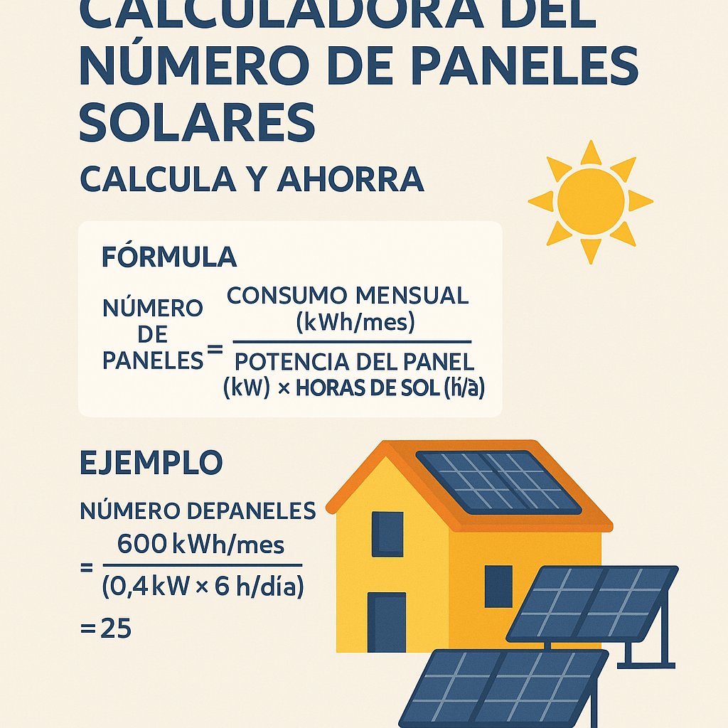
Core formulas and variable definitions
Below are the principal formulas used operationally. Each formula is shown with variables defined and typical nominal values for design engineering.Required DC array power (W):
- E_target_kWh_per_day: daily consumption target in kWh/day. Typical residential: 8–30 kWh/day; small commercial: 50–500 kWh/day.
- H_peak_sun_hours: average daily equivalent full-sun hours at site. Typical ranges: 2.5–6.0 h/day depending on latitude and climate; see irradiance table below.
- η_system: overall system performance factor (decimal). Typical 0.65–0.85. Conservative design often uses 0.70–0.75 to account for real-world losses.
Number of panels (integer):
- P_panel_W: panel nominal (STC) power in watts (e.g., 300 W, 370 W, 450 W).
- ceil(): rounding up to nearest whole panel to ensure energy target is met.
Estimated AC energy produced per day (kWh):
- E_AC_kWh: expected delivered energy to the AC side per day, accounting for losses.
Array area (m²):
- Panel_area_m2: typical panel footprint; e.g., for a 370 W 72-cell panel ≈ 1.95–2.2 m² depending on form factor.
Approximate capital cost (currency):
- Cost_per_panel: vendor price per panel (typical range USD 100–350 depending on wattage and manufacturer).
- BOS_cost: balance-of-system items (inverter, racking, wiring, protections). Commonly 30–60% of total installed cost.
- Installation_cost: labor and commissioning.
Typical variable values and loss factors
For accurate calculations, the system efficiency η_system should be decomposed. Typical loss factors are listed with recommended engineering defaults for initial sizing.| Loss factor | Typical range (%) | Design default (%) | Notes |
|---|---|---|---|
| Inverter efficiency | 95–99 | 97 | Based on transformerless string inverter performance at nominal load. |
| Soiling | 1–8 | 4 | Urban moderate pollution; use higher values in dusty environments or with infrequent cleaning. |
| Mismatch and degradation | 1–5 | 2 | Initial mismatch among modules and early degradation. |
| Temperature and irradiance effects | 2–7 | 4 | Depends on temperature coefficient and local ambient temperatures. |
| Shading | 0–20 | 0–10 (site-dependent) | Site-specific; partial shading requires string or optimizer-level mitigation. |
| Wiring and transformer losses | 1–3 | 1.5 | Based on conductor sizing and AC distribution distance. |
| Other system losses (MPPT efficiency, connector losses) | 1–3 | 1.5 | Includes module-to-inverter MPPT inefficiency and connector contacts. |
Reference tables for panel characteristics and site irradiance
Below are common panel nominal powers, typical dimensions, and average efficiencies for current commercial modules.| Panel model class | Nominal power (W) | Efficiency (%) | Typical area (m²) | Typical weight (kg) |
|---|---|---|---|---|
| Residential mono PERC 60-cell | 300–330 | 18–20 | 1.6–1.8 | 18–22 |
| Residential mono half-cut 66-cell | 360–380 | 20–22 | 1.8–2.0 | 20–24 |
| Commercial mono 72-cell | 370–420 | 20–22.5 | 1.95–2.2 | 22–28 |
| High-power modules (M10/TOPCon) | 450–600 | 22–24.5 | 2.2–2.8 | 26–35 |
| Location (representative) | Approx. annual average peak sun hours (h/day) | Seasonal range (h/day) | Source guidance |
|---|---|---|---|
| Seville, Spain | 5.3 | 3.6–7.2 | PVGIS / Meteonorm |
| Madrid, Spain | 4.6 | 3.2–6.4 | PVGIS |
| Berlin, Germany | 2.9 | 1.4–4.7 | PVGIS |
| London, UK | 2.6 | 1.2–4.4 | PVGIS |
| New York, USA | 4.1 | 2.3–5.9 | NREL / PVWatts |
| Los Angeles, USA | 5.5 | 4.0–7.0 | NREL / PVWatts |
| Phoenix, USA | 6.2 | 5.2–7.6 | NREL |
| Sydney, Australia | 4.8 | 3.6–6.0 | PVGIS / Bureau of Meteorology |
| Cape Town, South Africa | 5.0 | 3.8–6.5 | PVGIS |
| Tokyo, Japan | 4.1 | 2.6–5.6 | PVGIS |
Detailed worked examples
Below are two complete real-world sizing examples. Each example shows stepwise calculations, assumptions, intermediate results, and final decisions.Example 1 — Residential roof in Madrid, Spain
Project brief:- Location: Madrid metropolitan area.
- Metered monthly consumption: 360 kWh/month.
- Goal: Offset 100% of grid consumption with PV generation (grid-tied, no battery initially).
- Available roof area: 25 m² on south-facing roof; tilt approx. 30°.
- Preferred module: 370 W 72-cell module with 2.0 m² area, manufacturer temp coefficient -0.35%/°C.
From PVGIS, Madrid annual average H ≈ 4.6 h/day at optimal tilt.
Step 3 — System efficiency assumptions:- Inverter efficiency = 97% (0.97)
- Soiling = 4% (0.96)
- Temperature and irradiance effects = 4% (0.96)
- Wiring/mismatch/other = 3% (0.97)
Array_area_m2 = 9 * 2.0 = 18 m², which fits within available 25 m² roof area.
Step 7 — Expected daily AC production:E_AC_kWh = (9 * 370 * 4.6 * 0.82) / 1000 = (9 * 370 * 3.772) / 1000 ≈ (9 * 1,395.64) / 1000 ≈ 12.56 kWh/day
This slightly exceeds the 12 kWh/day target, providing a small margin.Step 8 — Economic quick estimate:- Panel cost estimation: 9 * USD 180 = USD 1,620
- BOS + inverter + racking + wiring estimate: USD 3,000 (varies)
- Installation & permits: USD 1,500
- Estimated installed cost: ~USD 6,120
- Verify string-inverter voltage/current compatibility and roof load-bearing capacity.
- Perform shading analysis for early morning/late afternoon obstructions; if shading is present, consider module-level power electronics or microinverters.
- Check local permitting and building codes (e.g., EU directives and national grid-connection rules).
Example 2 — Small commercial rooftop in Los Angeles, USA
Project brief:- Location: Los Angeles downtown commercial building.
- Metered monthly consumption: 9,000 kWh/month.
- Goal: Offset 60% of annual consumption with rooftop PV; battery not included initially.
- Available roof area: 400 m²; roof tilt flat with racking to 10° south orientation.
- Preferred module: 400 W high-efficiency commercial module; area 2.1 m².
From NREL PVWatts, Los Angeles H ≈ 5.5 h/day for typical tilt.
Step 3 — System efficiency assumptions:- Inverter efficiency = 98% (0.98)
- Soiling = 3% (0.97)
- Temperature effects = 5% (0.95) — commercial rooftop can be hotter
- Wiring/mismatch = 2% (0.98)
Array_area_m2 = 94 * 2.1 = 197.4 m²; available roof area is 400 m², so adequate area exists including spacing and maintenance aisles.
Step 7 — Expected daily AC production:E_AC_kWh = (94 * 400 * 5.5 * 0.86) / 1000 = (94 * 400 * 4.73) / 1000 ≈ (94 * 1,892) / 1000 ≈ 177.85 kWh/day
Matches target within rounding.Step 8 — Installer-level considerations:- String sizing and inverter selection: choose one or multiple inverters; consider three-phase commercial inverter topology for reduced balance-of-system complexity.
- Electrical infrastructure: verify available point-of-connection and utility interconnection requirements (e.g., feed-in limits).
- Roof structural assessment: evaluate ballast racking loads if using non-penetrating mounts and live load considerations for maintenance access.
- Panels: 94 * USD 200 = USD 18,800
- Inverter(s) and BOS: approx. USD 30,000
- Installation, structural works, permits: USD 20,000
- Estimated installed cost: USD 68,800
Refinements: temperature, tilt, shading, and degradation
Technical design must refine the basic sizing by accounting for:- Temperature coefficient: module output reduces with cell temperature. If the module temp coefficient is -0.35%/°C and site operating cell temperature is 45°C vs STC 25°C, derating due to temperature = 20°C * 0.35% = 7% loss. Use vendor NOCT data for precise modeling.
- Tilt and orientation mismatch: deviation from ideal tilt/azimuth reduces effective H. Use incident irradiance models to compute relative losses for tilted surfaces.
- Shading analysis: conduct a horizon and near-field shading study with tools or onsite topographic survey; express shading in percent of irradiance loss and address with layout design or module-level electronics.
- Annual degradation: PV modules degrade over time. Typical warranties specify ≤0.7%/year or ≤0.5%/year for newer technologies. Factor expected degradation into long-term energy production estimates and financial modeling.
Regulatory and standards references
Design and installation should conform to applicable international and national standards. Key normative references:- IEC 61215 — Crystalline silicon terrestrial photovoltaic (PV) modules — Design qualification and type approval. Source: International Electrotechnical Commission: https://www.iec.ch
- IEC 61730 — PV module safety qualification (electrical and mechanical safety): https://www.iec.ch
- IEC 61701 — Salt mist corrosion testing for PV modules in coastal environments: https://www.iec.ch
- IEC 60364 series — Low-voltage electrical installations (relevant sections for PV handling and earthing): https://www.iec.ch
- NEC (NFPA 70) — US National Electrical Code, Article 690 and 705 for PV system installations and interconnections: https://www.nfpa.org/NEC
- NREL PVWatts and system modeling guidance for resource estimation: https://pvwatts.nrel.gov/
- PVGIS — Solar resource and PV performance modeling for Europe, Africa, and Asia: https://re.jrc.ec.europa.eu/pvg_tools/
- IEA PVPS reports — International Energy Agency Photovoltaic Power Systems Programme analyses and best practices: https://iea-pvps.org/
Practical UX considerations for calculator interfaces
When implementing a customer-facing calculator, include:- Input validation and units: accept kWh/month, kWh/day, or meter readings; provide clear unit labels and automatic conversions.
- Location lookup: integrate geolocation or a search box to retrieve local irradiance data programmatically from trusted services (e.g., PVGIS, NREL) for accurate H values.
- Loss factor presets: provide standard presets (conservative, typical, optimistic) but allow expert users to customize each loss term.
- Visual outputs: show a range of expected generation (P50/P90) and a sensitivity analysis for panel count vs. system efficiency.
- Exportable design summary: generate a PDF with assumptions, calculations, bill-of-materials estimate, and regulatory checklist for permitting.
Quality assurance and field verification
Before commissioning, perform:- String-level IV curve tests to verify array power matches modeled output within tolerance.
- Thermographic inspections post-commissioning to detect hot spots and faulty solder joints.
- Performance ratio (PR) monitoring for the first 12 months to detect systematic underperformance (PR target 0.75–0.90 depending on climate and technology).
- Periodic maintenance plan: cleaning schedule, inverter firmware updates, and inspections to preserve design assumptions on soiling and degradation.
Frequently used calculation checklist for engineers
Use this checklist when sizing a PV array:- Confirm metered consumption and desired offset percentage.
- Obtain accurate site irradiation data for planned tilt/azimuth.
- Select module type and obtain STC power, efficiency, area, and temperature coefficient.
- Define all system loss contributors with engineering justification.
- Calculate Required_DC_W and Number_of_panels; evaluate mechanical layout feasibility.
- Select inverter topology and verify electrical compatibility (MPP voltage, string length, overcurrent protection).
- Perform shading analysis; if shading significant, specify optimizers or microinverters.
- Prepare permit-ready documentation and safety plan in accordance with local and international codes.
External resources and further reading
For authoritative technical resources and tools:- NREL PVWatts — simple site-specific PV energy production calculator and methodology: https://pvwatts.nrel.gov/
- PVGIS — European Commission Joint Research Centre photovoltaic geographic information system: https://ec.europa.eu/jrc/en/pvgis
- International Electrotechnical Commission (IEC) standards catalogue — search for IEC 61215, 61730: https://www.iec.ch/standards
- IEA PVPS — technical reports on PV system performance and best practices: https://iea-pvps.org/
- US National Electrical Code — NFPA 70 — for interconnection and safety requirements (Article 690/705): https://www.nfpa.org/NEC
- EnergySage — marketplace and educational resources on PV economics and system sizing: https://www.energysage.com/solar/