Fast, free, and accurate kVA-to-amperes calculator for international electrical sizing and load analysis applications professionals.
Engineers require precise conversions for transformers, generators, and distribution circuits across varied voltages and standards.
No se pudo generar la calculadora automáticamente.
El bloque generado no cumplió la estructura mínima requerida: falta alguno de los bloques <style>, <section>, <script> o JSON-LD.
El bloque generado no cumplió la estructura mínima requerida: falta alguno de los bloques <style>, <section>, <script> o JSON-LD.
Basics of kVA, kW and Electrical Current
Understanding apparent power (kVA) and current (A) is fundamental for electrical design, transformer and generator selection, and protection coordination. Apparent power (S) in kilovolt-amperes represents the product of line voltage and line current for sinusoidal systems; it does not include power factor. Real power (P) in kilowatts accounts for power factor (PF). Correct conversion between these magnitudes avoids undersized conductors and mis-specified protective devices. Electrical systems commonly encountered:- Single-phase, line-to-neutral voltage (domestic and small commercial).
- Three-phase, delta or star (wye) systems for industrial and large commercial installations.
- Resistive, inductive, and non-sinusoidal loads, which affect apparent vs real power relationships.
Essential Conversion Formulas (kVA ↔ Amperes)
Below are the standard formulas used to convert apparent power in kVA to line current in amperes. These use plain HTML text for operators and variables.Single-phase systems
Single-phase apparent-power to current:I (A) = (kVA × 1000) ÷ V
I (A) = (kW × 1000) ÷ (V × PF)
Three-phase systems (balanced)
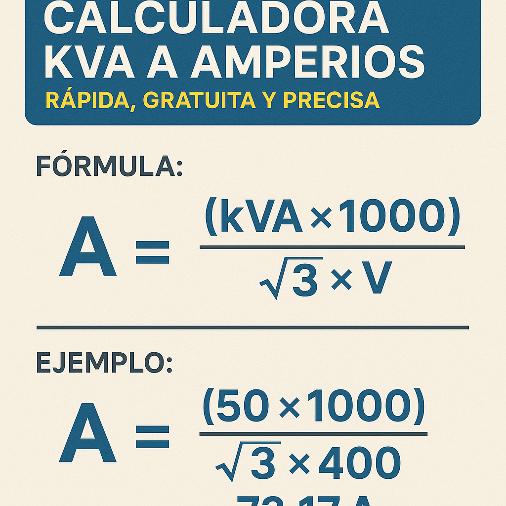
Three-phase apparent-power to line current:I (A) = (kVA × 1000) ÷ (√3 × V)
I (A) = (kW × 1000) ÷ (√3 × V × PF)
Variable definitions and typical values
- kVA — Apparent power in kilovolt-amperes (kVA). Typical values: 1 kVA to several MVA for industrial transformers. Example common sizes: 5, 10, 15, 25, 50, 100, 250, 500 kVA.
- kW — Real power in kilowatts (kW). For resistive loads PF ≈ 1. For motors PF ≈ 0.8 leading/lagging.
- I (A) — Line current in amperes (A).
- V — Line voltage in volts (V). Typical distribution voltages: 120 V, 230 V, 400 V, 415 V, 480 V, 600 V, 6.6 kV, etc.
- PF — Power factor (unitless). Typical engineering defaults: lighting ~0.9–1.0, motors ~0.8–0.95 lagging, general office ~0.95.
- √3 — Square root of three (≈ 1.732), used for balanced three-phase line-to-line calculations.
Practical conversion tables (common sizes)
| kVA | Single-phase 120 V (A) | Single-phase 230 V (A) | Three-phase 230 V (A) | Three-phase 400 V (A) | Three-phase 480 V (A) | Three-phase 600 V (A) |
|---|---|---|---|---|---|---|
| 1 | 8.33 | 4.35 | 2.51 | 1.44 | 1.20 | 0.96 |
| 2 | 16.67 | 8.70 | 5.02 | 2.88 | 2.40 | 1.92 |
| 5 | 41.67 | 21.74 | 12.55 | 7.20 | 6.00 | 4.80 |
| 10 | 83.33 | 43.48 | 25.10 | 14.39 | 12.00 | 9.60 |
| 15 | 125.00 | 65.22 | 37.65 | 21.59 | 18.00 | 14.40 |
| 25 | 208.33 | 108.70 | 62.75 | 36.00 | 30.00 | 24.00 |
| 50 | 416.67 | 217.39 | 125.51 | 72.01 | 60.00 | 48.00 |
| 100 | 833.33 | 434.78 | 251.02 | 144.02 | 120.00 | 96.00 |
| 250 | 2083.33 | 1086.96 | 627.55 | 360.05 | 300.00 | 240.00 |
| 500 | 4166.67 | 2173.91 | 1255.10 | 720.10 | 600.00 | 480.00 |
| kVA | Three-phase 208 V (A) | Three-phase 415 V (A) | Three-phase 690 V (A) | Generator sizes example |
|---|---|---|---|---|
| 10 | 27.78 | 13.93 | 8.38 | Small emergency gensets |
| 25 | 69.44 | 34.82 | 20.95 | Small commercial gensets |
| 50 | 138.89 | 69.63 | 41.90 | Medium commercial |
| 100 | 277.78 | 139.27 | 83.80 | Large commercial |
| 500 | 1388.89 | 696.34 | 419.00 | Industrial plants |
How to use a kVA → Amp calculator: required inputs and expected outputs
Essential inputs:- Apparent power in kVA (S).
- Nominal voltage (V): specify whether line-to-line or line-to-neutral.
- System configuration: single-phase or three-phase (balanced assumption).
- Optionally, power factor (PF) if you are converting kW to amps, or need to account for real power.
- Line current per phase (A) with rounding rules applied.
- Recommendations for overcurrent device sizing (percentages and rules) and conductor ampacity (reference standards).
- Notes on continuous load adjustments, harmonics or non-sinusoidal effects if inputs indicate non-linear loads.
Accuracy considerations, derating and safety margins
A calculator gives an ideal balanced, sinusoidal estimate. Field reality adds complexity:- Continuous loads — many standards (for example NFPA 70 / NEC) require sizing protection and conductors at 125% of continuous load current. Verify local code requirements before final selection.
- Power factor — if you start from kW or have poor PF, current will be higher for the same kW. Use accurate measured or manufacturer PF values.
- Harmonics and non-sinusoidal currents — harmonic distortion increases RMS current without increasing real power proportionally; consider harmonic factors and derating for neutrals and conductors.
- Ambient temperature and bundling — conductor ampacity is affected by ambient temperature and how many conductors are grouped. Apply correction factors from relevant ampacity tables.
- Startup/current inrush — motors and transformers have transient inrush currents exceeding steady-state; protection and generator sizing must account for starts.
Example calculations (real cases with full steps)
Example 1 — Three-phase distribution transformer: 50 kVA at 400 V
Problem statement:- Transformer rated 50 kVA feeding balanced three-phase load at 400 V (line-to-line).
- Determine line current per phase in amperes.
- Provide recommended minimum breaker size assuming continuous operation per NEC general practice (use 125% multiplier as engineering guideline; verify local code).
1) Use three-phase apparent power formula: I (A) = (kVA × 1000) ÷ (√3 × V)
2) Substitute values: I = (50 × 1000) ÷ (1.732 × 400)
3) Compute denominator: 1.732 × 400 = 692.8
4) Compute numerator: 50 × 1000 = 50,000
5) I = 50,000 ÷ 692.8 ≈ 72.11 A
- For continuous load, multiply by 125%: 72.11 × 1.25 = 90.14 A.
- Select next standard breaker or fuse rating: typical standard sizes are 80 A, 100 A. Choose 100 A breaker to meet continuous load guideline.
Example 2 — Single-phase commercial supply: 18 kVA at 230 V
Problem statement:- Single-phase feed for a commercial tenant is rated at 18 kVA, at 230 V line voltage.
- Compute the current and propose an MCB rating for non-continuous general loads.
1) Single-phase formula: I (A) = (kVA × 1000) ÷ V
2) Substitute values: I = (18 × 1000) ÷ 230
3) Numerator: 18,000. Divide: 18,000 ÷ 230 ≈ 78.26 A
Result: Steady-state current ≈ 78.26 A. Overcurrent selection:- If load is non-continuous, standard practice is to use nearest standard MCB/MCB rating above calculated current. Available standard ratings include 80 A and 100 A.
- Because 78.26 A ≈ 80 A, choose 80 A MCB if permitted by local rules. If continuous loads are present, size at 1.25 × 78.26 ≈ 97.83 A → select 100 A.
Generator sizing and starting currents: practical adjustments
When sizing generators from kVA to current, consider:- Inrush current for motors can be 3–7 × rated current; locked-rotor current and starting technique (direct-on-line, star-delta, soft-start) must be considered.
- Generator kVA rating is an apparent power rating; for standby generators, real kW capability depends on power factor and available prime vs standby ratings.
- Load diversity and coincidence factors allow reduction in generator sizing for multiple loads that do not start simultaneously; perform a diversity study for large facilities.
Non-ideal conditions and corrections: harmonics, PF and unbalanced loads
Non-ideal loads can invalidate the simple balanced-sinusoidal formulas:- Harmonics: Non-linear loads create harmonic currents that increase conductor heating. Use distortion factors (Ith/Iav) and apply harmonic derating to conductors and transformers.
- Unbalanced loads: If phase currents differ, compute actual per-phase currents individually by converting each phase apparent power to current or use measured currents.
- Power factor correction: For improved PF, add capacitors or synchronous condensers. When specifying equipment, deliver both kW and kVA requirements to vendors.
Recommended workflow for accurate engineering use of a kVA-to-Amp calculator
Follow these steps for a reproducible engineering result:- Collect accurate input data: measured kW/kVA, voltage, PF, and system configuration.
- Decide whether calculations assume balanced, sinusoidal conditions; if not, include corrections.
- Run conversion using the appropriate formula (single-phase or three-phase).
- Apply code-required safety multipliers (e.g., continuous load factors) and correction factors (ambient, conductor grouping).
- Select protective device and conductor using local code ampacity tables and manufacturer data.
- Document assumptions: PF, continuous/non-continuous, ambient temperature, harmonic content, tolerance and rounding rule.
Common pitfalls and how to avoid them
- Mixing line-to-line and line-to-neutral voltage: always confirm whether voltage input is line-to-line (used in three-phase formula) or line-to-neutral for single-phase calculations.
- Using kW in place of kVA without adjusting for PF: this underestimates current when PF < 1.
- Ignoring continuous-load requirements: many code jurisdictions mandate 125% sizing for continuous loads when selecting overcurrent protection.
- Neglecting harmonics: can cause premature overheating despite correct apparent power calculations.
- Selecting protection too close to calculated current: allow margin and use standard device sizes, accounting for inrush and short-time withstand requirements.
Standards, references and authoritative resources
The following documents offer normative requirements and technical details used in professional practice. Consult the latest editions and national variants when designing or installing equipment.- NFPA 70 — National Electrical Code (NEC), published by the National Fire Protection Association: https://www.nfpa.org/nec
- IEC 60076 — Power Transformers (series) — relevant for transformer ratings and loading: https://www.iec.ch/standards
- IEC 60364 — Electrical Installations of Buildings — for installation rules (international): https://www.iec.ch/standards
- IEEE Standards — relevant documents include IEEE Std 141 (Electrical Power Distribution), IEEE Std 399 (Brown Book) for industrial power systems: https://standards.ieee.org
- NEMA — National Electrical Manufacturers Association provides equipment ratings and guidance: https://www.nema.org
- EN and national wiring regulations — consult local authority having jurisdiction for mandatory requirements.
Frequently used numeric examples and quick-reference values
| Device / Load | Typical PF | kVA per kW (approx.) | Notes |
|---|---|---|---|
| Resistive heater | 1.00 | 1.00 | kW = kVA; currents minimal reactive component |
| Incandescent lighting | 0.95–1.00 | ≈1.05–1.00 | Some small reactive elements in ballasts |
| Fluorescent lighting (electronic ballast) | 0.90–0.99 | ≈1.01–1.11 | Depends on correction in ballast |
| Large induction motor | 0.75–0.90 | ≈1.11–1.33 | Low PF at light loads; consider starting currents |
| Variable frequency drive (VFD) | 0.95–0.99 | ≈1.01–1.05 | May inject harmonics; check manufacturer's data |
| Transformers (no-load) | N/A | N/A | Specify kVA rating; loading defines currents |
Final engineering recommendations
- Always record and preserve the assumptions used for any kVA-to-amp conversion in project calculations.
- Cross-check calculator outputs with manufacturer catalogues and with ampacity tables from applicable regulations.
- Use caution with non-sinusoidal loads: perform harmonic analysis when harmonic-producing equipment exceeds a small percentage of the facility load.
- For generators, conduct a starting and transient study; do not rely solely on steady-state kVA conversion for sizing.
- When in doubt, consult a licensed electrical engineer or the equipment manufacturer; national codes (e.g., NEC) take precedence for legal compliance.
Useful quick-check checklist before final specification
- Confirm voltage type and level (line-to-line or line-to-neutral).
- Confirm system configuration (single-phase/three-phase) and balance assumption.
- Confirm kVA or kW input and whether PF must be applied.
- Apply continuous load multipliers and ambient/installation correction factors.
- Check harmonics and inrush currents for motors/transformers.
- Select protective devices and conductors based on corrected ampacity and device ratings.
- Document margins, rounding, and final selections for audits and maintenance.
- NFPA 70: National Electrical Code — NFPA. URL: https://www.nfpa.org/nec
- IEC standards catalogue — International Electrotechnical Commission. URL: https://www.iec.ch/standards
- IEEE Standards and Publications — IEEE. URL: https://standards.ieee.org
- NEMA publications and equipment standards — NEMA. URL: https://www.nema.org
- Provide an interactive step-by-step calculator UI specification to embed in your engineering documentation.
- Generate downloadable spreadsheets with built-in corrections and code-based ampacity lookups for your region.
- Run additional worked examples for specific voltages, PF values, or generator start profiles.